Romanian ZPM (Zero Point Module)

  • Topic Is Locked
  • 3.4K Views
  • Last Post 12 February 2023
  • Topic Is Solved
Fighter posted this 07 February 2023

This is the imported thread (from the old aboveunity site) about my ZPM:

For references I will keep the original posting date for every imported post.

Note: This thread is public, everyone can see it, even the visitors which are not members here.

For the posts made by former aboveunity members which are not members on our site I'll use a member placeholder named UndisclosedMember.

Regards,

Fighter

"If you want to find the secrets of the universe, think in terms of energy, frequency and vibration."
Nikola Tesla
  • Liked by
  • Jagau
  • Inception
Fighter posted this 02 August 2019

Hi guys,

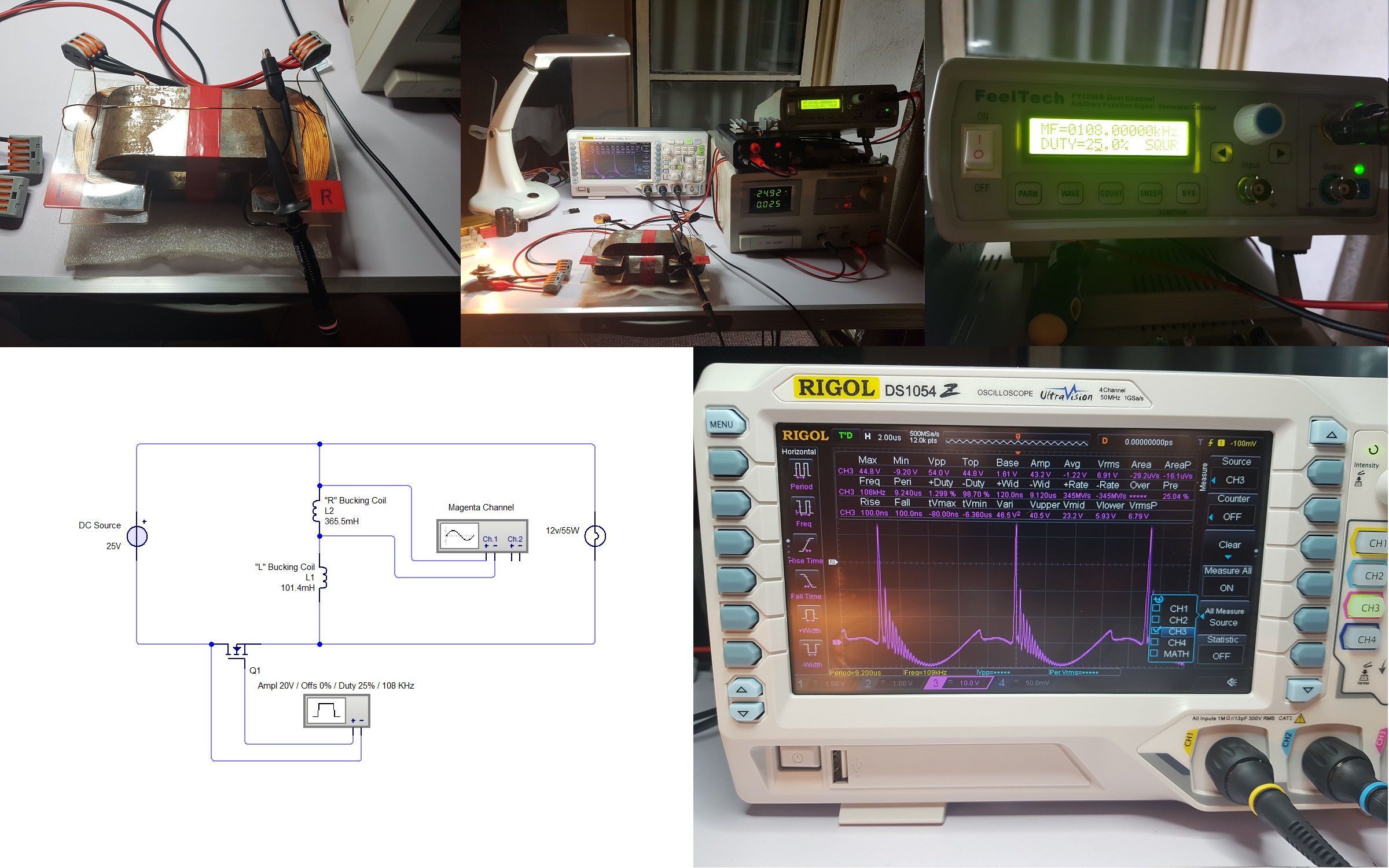
I'm going to vacation for two weeks so I'll not be able to do experiments for a while. But before going I wanted to take with me a screenshot of all the signals in ZPM in the same time to see the interaction between coils depending on input signal and how the output depends on all these so I can understand those interactions and think about them for possible efficiency improvements.

As you know all the ground clips from the four channels of the oscilloscope are linked together so it's not possible to just put oscilloscope's probes on input, coils and output in the same time because that would short-circuit them but the idea was to put each probe at a time while keeping the base-time so at the end the waveforms can be unified in a single image.

So I'll post images with every measurement (including measurement schema) and at the end I'll post the "unified" image.

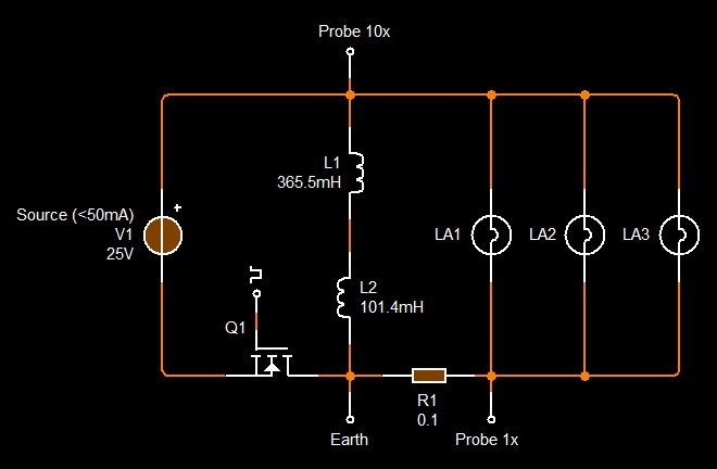
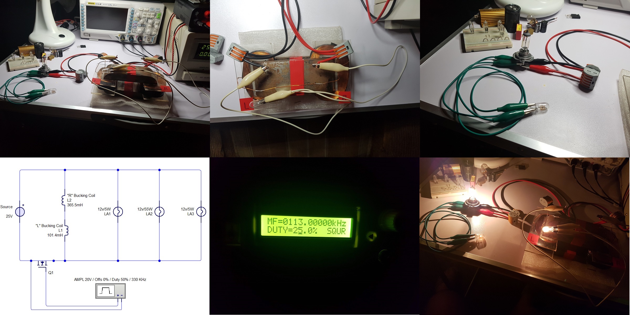
This is for input, basically the signal on the MOSFET's gate as the function generator is driving it:

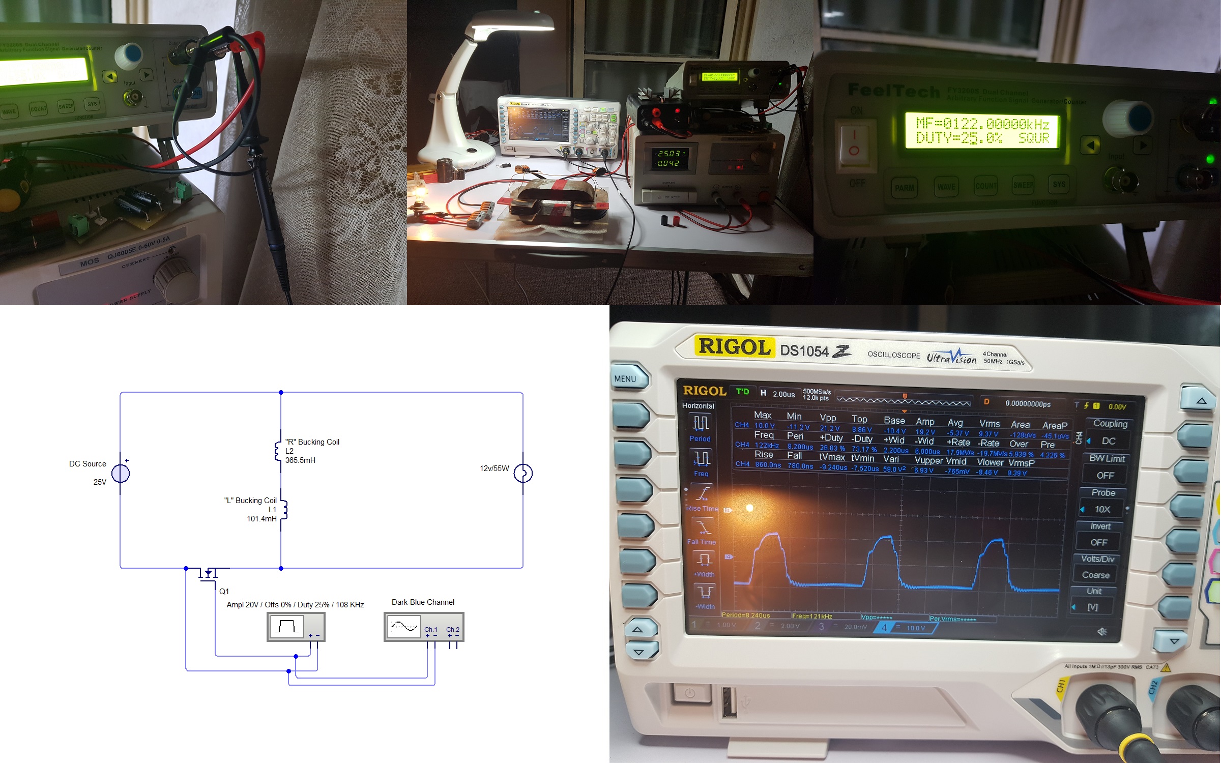
This is for "L" coil, the smaller coil:

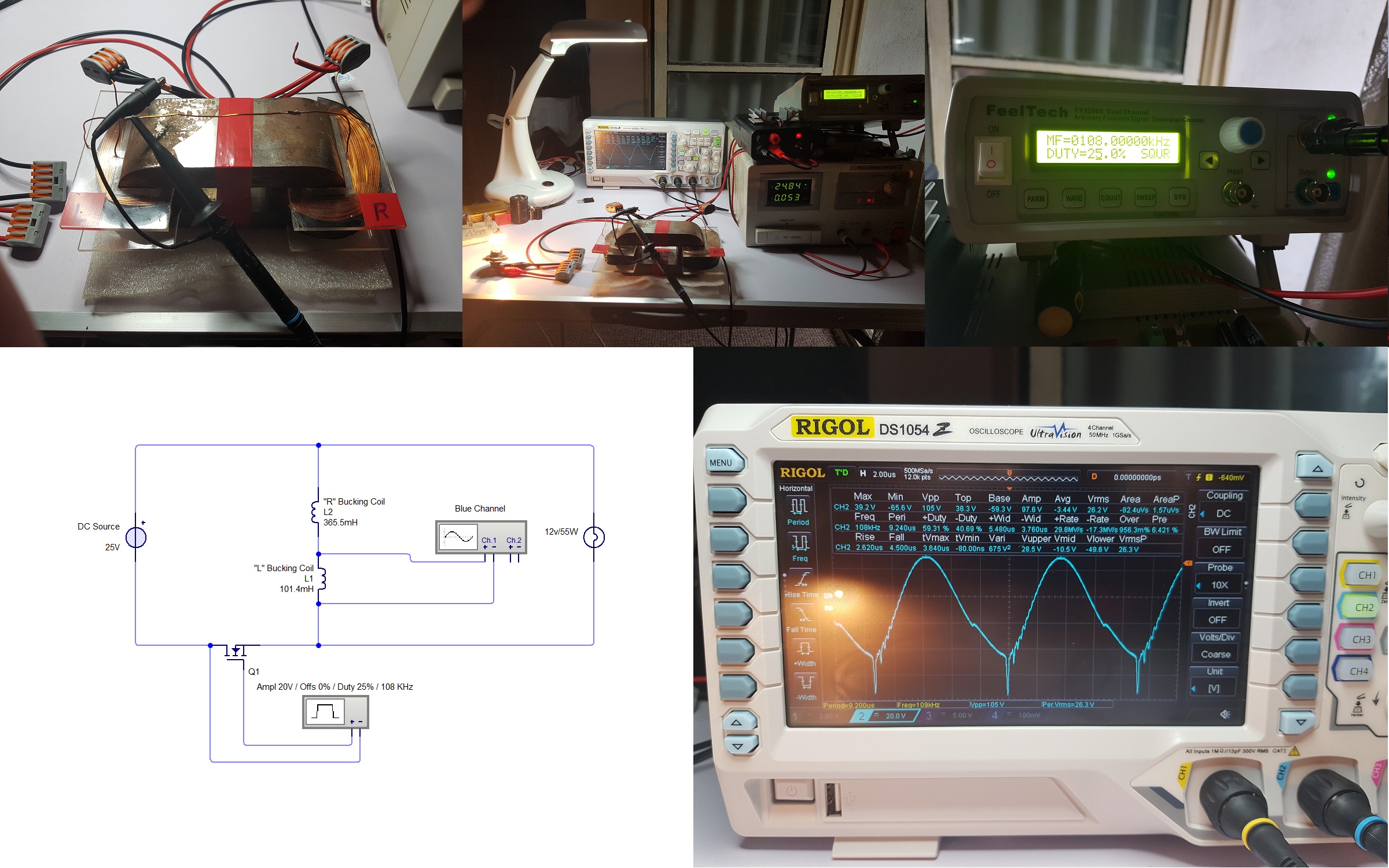
This is for "R" coil, the bigger coil:

And this is for output, basically coil "L" plus coil "R:

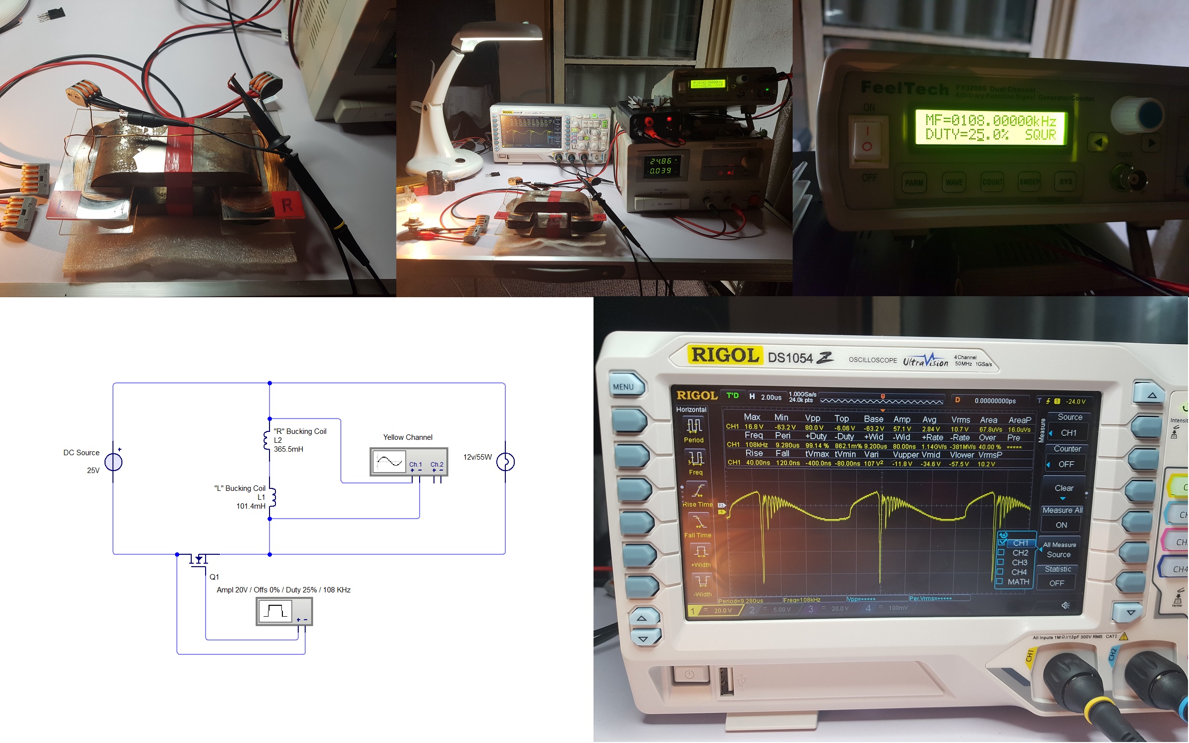
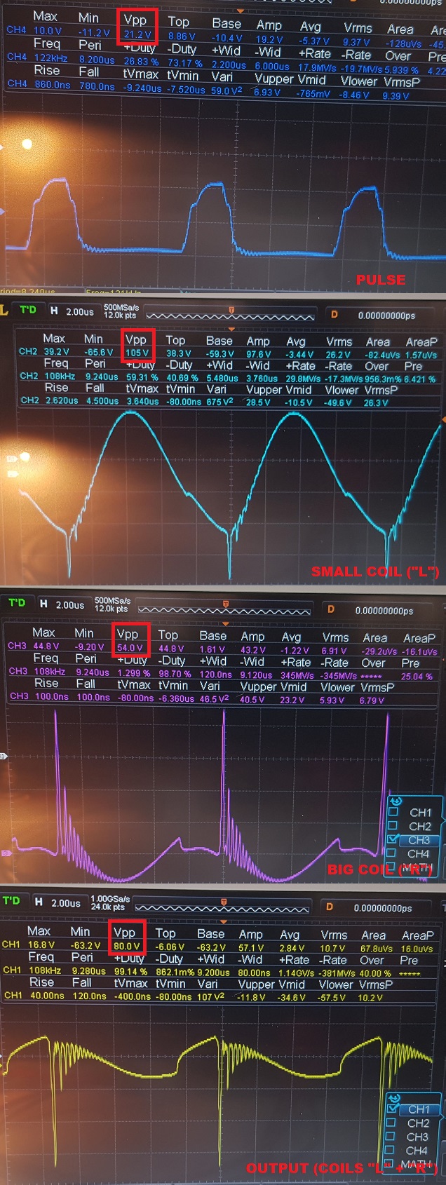
And this is the "unified" image, tried to sync the scope images to show the waveforms from each measurement with a common time-base. As you can see each measurement has 2 microseconds time-base but be aware about the amplitude of each waveform, that's changed for each measurement in order to show more details.So in order to compare the amplitudes of waveforms check the Vpp value for each, I placed a red rectangle on that value in each image:

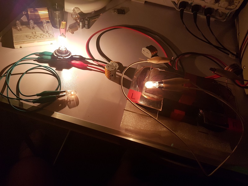
Also I found a strange thing about the device, it seems to have "preferences" on how it's powering the loads.

But it's very late now and I need to prepare the presentation of my finding (including a scheme), I'll do it tomorrow.

Until then take a look on this image and observer the two smaller light-bulbs (12V/5W); they are placed in parallel on ZPM's output just like the bigger light-bulb (12V/55W) and the wires connecting them to the output are identical. The only difference between them : one is connected on ZPM's output before the 12V/55W light-bulb while the other is connected after the 12V/55W light-bulb. Even if these two 12V/5W light-bulbs are connected to the ZPM's ouptut, the luminosity of one is much stronger than the luminosity of the other. Maybe there is a conventional explanation for this but I did some research and didn't found that explanation. It's like Mr. Preva experiment but both light-bulbs (with different luminosity) are actually on the same branch:

"If you want to find the secrets of the universe, think in terms of energy, frequency and vibration."
Nikola Tesla
  • Liked by
  • Inception
UndisclosedMember posted this 03 August 2019

Hey Fighter,

Excellent effort as always. Thank you.

Next time, when you get time, if you're able to supply the Voltage and Current measurements for that node:

Input:

Already done.

Output:

As you already know, measurements need to be Mean or Average, see here.

P.S: I was sortta hoping others would join in on this?

  • Liked by
  • Inception
Vidura posted this 03 August 2019

Hey all, When I was in Europe last week o had ordered two AMCC cores, but they didn't arrive in time, for one day late I couldn't bring them in this journey. As you might know in my place there are no sellers for this material, so I don't know still when I can get the core to give this experiment a try. Hopefully some others who have access to Metglass cores will join and help to bring more light on this. Vidura

Vidura

  • Liked by
  • Inception
UndisclosedMember posted this 03 August 2019

cool ,  - well hopfully i will have caught up by the time you get back. -   just too confirm though, you are using a square wave input. - of about 25% ?, -  do you have much margin for error with that figure ?.   .   also any other buttock clenching facts you can think might help ?

  • Liked by
  • Inception
Fighter posted this 03 August 2019

yes, square wave input. duty-cycle right now is 25% but before it was working also with 50%. about tips, I can think of only one thing right now, the procedure of finding the optimal frequency specific to your device, you will need to do frequency sweep 'cause for sure it will not be the same like the frequency of my device:

"If you want to find the secrets of the universe, think in terms of energy, frequency and vibration."
Nikola Tesla
  • Liked by
  • Inception
Fighter posted this 03 August 2019

Guys, I'll postpone the presentation of that anomaly about different light-bulbs luminosity, I'm out of time for now, preparing 'cause tomorrow I'll be on road the entire day, I'll post it within the next few days.

"If you want to find the secrets of the universe, think in terms of energy, frequency and vibration."
Nikola Tesla
  • Liked by
  • Inception
Vidura posted this 03 August 2019

When reviewing the latest scope shots posted by Fighter I found the following detail very interesting: It is about the ringing, with a frequency around 4Mhz; it called my attention that the first spike is synchronous with the BEMF when the switch turns off, at the peak of the "sine" wave, then the consecutive pulses are in the second quadrant of the wave( although it is not a sine shape, but pretty distortional ). We saw a similar effect in devices from Akula, Ruslan, and various others BTW coil builders, the pulses are applied in the falling potential area, when the magnetic force is building up. In the particular case of Fighters device the pulstrain could be caused by a coupling to the gate signal, triggered by the BEMF pulse. Of course this is only an assumption for the moment, until we get more testing results, trying some variations to determine how the effects are produced.

Vidura

Vidura

  • Liked by
  • Inception
Fighter posted this 06 August 2019

@Vidura, Yes I saw the same signal on others devices but I don't see a section of the signal having frequency so high (4Mhz), could you give more details ? Thanks.

And here is the anomaly I was talking about, basically when placing on the output of the ZPM three light-bulbs (two 12V/5W and one 12V/55W) the device seems to have a preference in how it powers up these light-bulbs.

More specific, the two 12V/5W light-bulbs are connected to the output using identical wires (just different colors - white and green) but their luminosity is different depending on their order. Basically the luminosity of the 12V/5W light-bulb placed after the 12V/55W light-bulb is much lower than the luminosity of a identical light-bulb placed before the 12V/55W light-bulb.

In the following images you can see details. As I said I was looking for a conventional explanation but didn't found one for the device's preference but I find it very intriguing:

"If you want to find the secrets of the universe, think in terms of energy, frequency and vibration."
Nikola Tesla
  • Liked by
  • Inception
Jagau posted this 06 August 2019

Hi fighter
I am just doing tests on coils not wound on metglass but on ferrite, in connection with your setup.
I noticed strange effects and I realized that the impedance of the load made a big difference in performance.
I am trying to check different scenarios. We talk again...
Jagau

  • Liked by
  • Inception
Fighter posted this 06 August 2019

I absolutely agree. Every time I put a different load I need to adjust the frequency, there is a optimal frequency for each type of load. But in this case the optimal frequency is already set but still I have two 12V/5W light-bulbs having different luminosity depending on their place related to the 12V/55W light-bulb on the ZPM's output. That's why I call this an anomaly because all those light-bulbs being powered from the same wires they should share the output power equally so both 12V/5W light-bulbs should have equal luminosity. But as you can see it's not working like this, the device seems to have some kind of preference in how it's providing its output power.

"If you want to find the secrets of the universe, think in terms of energy, frequency and vibration."
Nikola Tesla
  • Liked by
  • Inception
Close