@Vidura:
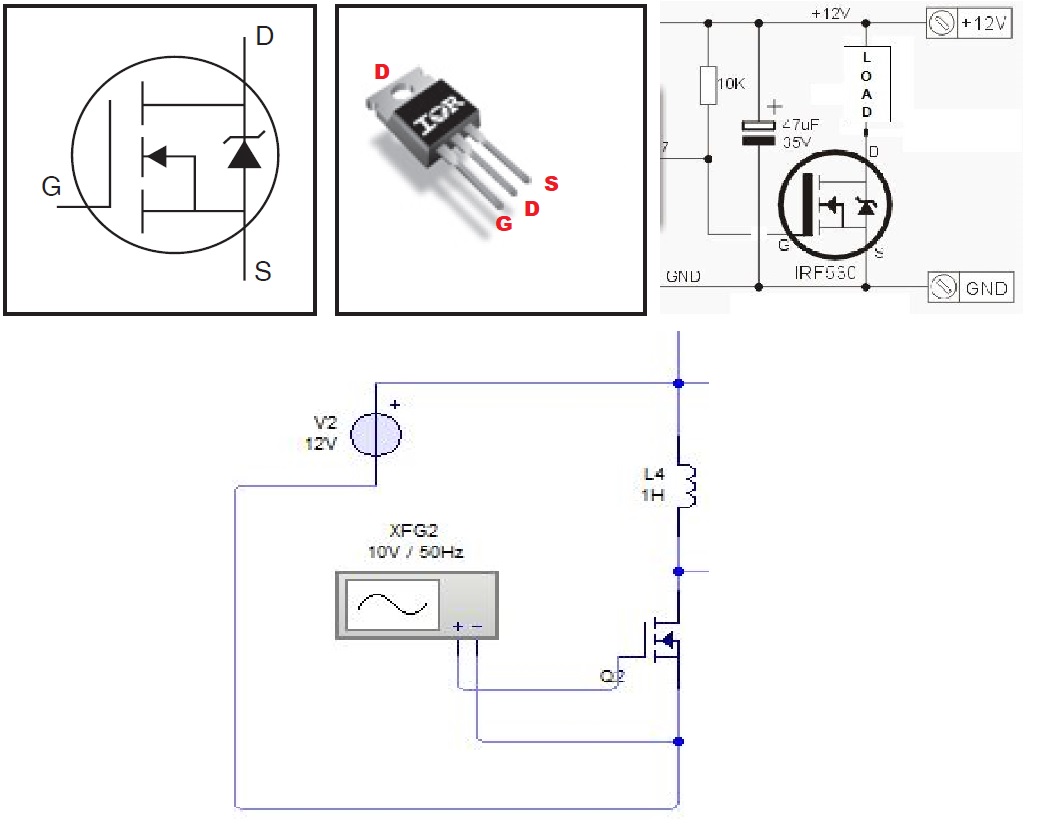
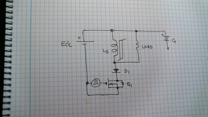
Hey Fighter, Please don't misunderstand my last post, I did not want to disregard anything of your work, as I stated my first impression was that it is AU. Take my comments for information purposes if you want, in some cases when we deal with small power levels all this things can be valuable, but if you could actually light two 35w bulbs, the influence from the SG can of course be neglected. Anyway here a suggestion for a very simple isolating switching application. Vidura
Hey, man, no worries, we're working with different devices having different behaviors here so any opinion is most than welcomed 🙂 Especially because I'm a beginner in electronics I'm always listening and learning.
About the driver I saw the video so should I use in the same time the optocuplers and the IRF3205ZPBFs I already have ? What optocuplers should I use for these transistors ? How would the schema for a signle-channel driver would look like ? Could it handle high frequencies like 700-800 KHz ? Thanks !
Hey CD,
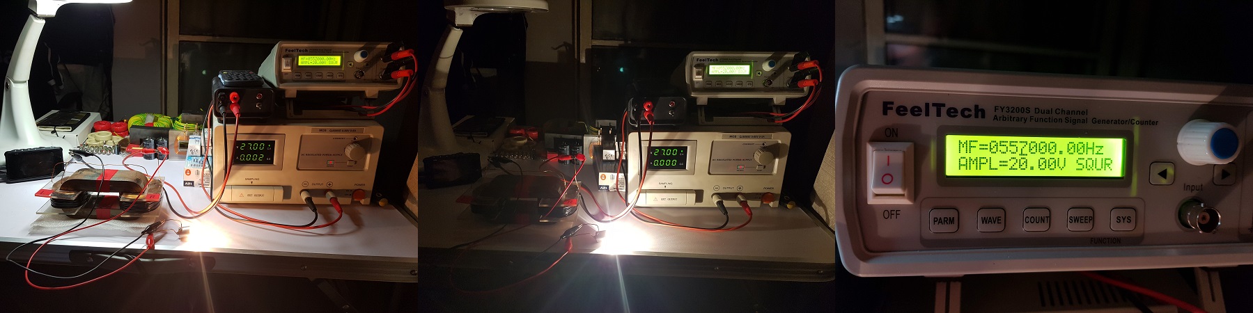
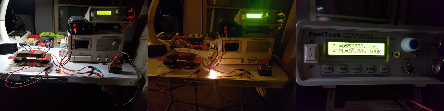
I honestly could not dedicate much time these days to the experiments, anyway I found some interesting effects. It is certainly worth to study more about this simple circuit. I dont have much varieties of cores , and there is no local supplier for metglas cores, so I simply used what I had at hand. There seems to build up a huge amount of recirculating- reactive power when resonant, and it happened very seldom that the bulbs lit, although that the power from the source should be present anytime. The voltage on the center tap between the coils becomes pretty high, and the two coils are always 180ª out of phase. Also I noted a important power drawing of the driver >2w @ 450kHz , using a IRF250 mosfet, it could be normal, I didn't make the calculation. When I lowered the frequency below 70 kHz the lamps(2x3W @6v) lit dimly at a lower harmonic . I guess the core and coils I used dont have the adecuate parameters for a successful replication.
Then I wanted to share this idea regarding the output power measurement. I remembered the researcher Robert Adams, who used to be a professional in calorimetric power measurements. It would be a possibility to use a small submergible water heater of convenient resistance (there are 12v models available), and take temperature readings for a exact amount of water, in a measured time interval the power / work can exactly be calculated. A very interesting comparison could be made with the change of temperature of the core, in the same time interval, in order to proof or disprove the theory of conversion of thermal energy in the core.
Vidura
So you saw almost the same behavior I presented here when the frequency is optimum but not low-amperage on your DC source's readings ? Could be something wrong with my source's reading and in the same time with the wattmeter's readings ?..
About reading watter temperature method, kind of need to buy anything because I don't have that 12V water heater and also I would need a waterproof temperature reader. I have a temperature reader on one of my multimeters but it's not waterproof and I never used it, don't know if it's accurate or not. Eventually I could use it to check if the temperature of the core drops, hopefully it can show me somehow accurate data...
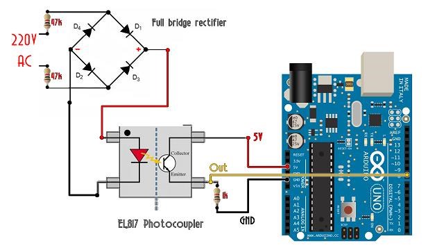
Hey Fighter, Thanks for sharing your work. I will answer your questions about optical isolating of the signal. But in first place I would suggest that you put a scope probe on the gate of the MOSFET, to check what signal is actually fed. What MOSFET you are using? optocouplers do only transfer signals, not power, and the frequency capability depends on the model. You have to be aware that the gate drive of a MOSFET require power, and this power increase proportional to the frequency. For this reason for practical implementation the frequency should better be kept lower. In the modul that I have shown in the video the power for this can be provided by the same supply, or by a dedicated separate source. And the driver is have a high speed optocoupler in the same chip integrated, for easy implementation. I can provide you a further simplified circuit if you want. Regards the back looping u would suggest to try with UF diodes rated for higher voltage, and a smaller capacitor, and some 100 nF Cap in parallel to smoot the spikes. Regards Vidura.
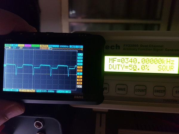
I'm using IRF3205ZPBFs on every channel, the driver has two channels but I'm currently using only one for this experiment. I disconnected the channel from ZPM and I put the oscilloscope on it, this is how it looks like, don't look like a very accurate squarewave but could be because of the high frequency:
About the driver I saw the video so should I use in the same time the optocuplers and the IRF3205ZPBFs I already have ? What optocuplers should I use for these transistors ? How would the schema for a signle-channel driver would look like ? Could it handle high frequencies like 700-800 KHz ? Thanks !
| "If you want to find the secrets of the universe, think in terms of
energy, frequency and
vibration." |
|
|
Nikola Tesla |