Romanian ZPM (Zero Point Module)

  • Topic Is Locked
  • 3.4K Views
  • Last Post 12 February 2023
  • Topic Is Solved
Fighter posted this 07 February 2023

This is the imported thread (from the old aboveunity site) about my ZPM:

For references I will keep the original posting date for every imported post.

Note: This thread is public, everyone can see it, even the visitors which are not members here.

For the posts made by former aboveunity members which are not members on our site I'll use a member placeholder named UndisclosedMember.

Regards,

Fighter

"If you want to find the secrets of the universe, think in terms of energy, frequency and vibration."
Nikola Tesla
  • Liked by
  • Jagau
  • Inception
Fighter posted this 20 June 2019

Hey dude! Nice work. But take note!
The internal instruments of some tear discs may be misinformed by extreme pulses.
Place the 4700-10000y capacitor in parallel with the output of the power supply. The power supply instrument already measures this current consumption.Vidura's comment is also helpful.

Thanks ! I will try to put 10,000uF capacitor in parallel with the source, thanks for the suggestion.

"If you want to find the secrets of the universe, think in terms of energy, frequency and vibration."
Nikola Tesla
  • Liked by
  • Inception
Fighter posted this 20 June 2019

Thank you for posting this Fighter and also CD_Sharp. Very insightfull.

All the best,

Vasile

You're welcome, please replicate it, test it and if your research can help in enhancing it please share your enhancements with us here. Thank you.

"If you want to find the secrets of the universe, think in terms of energy, frequency and vibration."
Nikola Tesla
  • Liked by
  • Inception
Fighter posted this 20 June 2019

And here I'm adding the oscilloscope data with probes set to 10X (on output you can see 3 x 12V/5W light bulbs).

Here the yellow channel probes are put on parallel with the light bulbs, meaning it's showing signal from both coils:

Note: for some unknown reason the blue channel is showing also some signal even if I disconnect its probes from oscilloscope, it's nothing wrong with the channel, it's the first case when I see it not showing a straight line when its probes are disconnected.

And here you can see the blue channel probes put on the small coil ("L") and the yellow channel probes put on the bigger coil ("R"):

This second image is the most interesting because it's showing the interaction between the two coils while ZPM is functioning.

"If you want to find the secrets of the universe, think in terms of energy, frequency and vibration."
Nikola Tesla
  • Liked by
  • Inception
Fighter posted this 20 June 2019

And here you can see photos of tests with halogen light bulbs.

This test is with one 12V/20W halogen light bulb, I had it put directly on the table and it was so hot that I noticed the table under the light bulb started to emit smoke, see the small yellow dot on the table in the last photo:

And the test below is with 2 x 12V/35W halogen light bulbs, as a temporary solution to avoid burning the table I put them on a testboard so they don't stay on the table but for now I can't test with them more than 2-3 minutes because for sure the plastic from the testboard will start to melt; the last image shows the luminozity of these two halogen lights when the lights in the room are turned off:

After these tests and after having a conversation with Cd_Sharp the conclusion is: this device can be scaled up and can provide power to standard 220V light bulbs.

Note: I intend to record a video to present a test with those two 12V/35W halogen light bulbs, hopefully I will have some time to do this in weekend, I'll post it here when it's ready.

"If you want to find the secrets of the universe, think in terms of energy, frequency and vibration."
Nikola Tesla
  • Liked by
  • Inception
cd_sharp posted this 20 June 2019

My friends, this can be feed-back looped as suggested. A cap is fed by the input power but also by one POC at a time like here , here and probably some other places.

If you know how to build such a device and you're not sharing, you're a schmuck! - Graham Gunderson

  • Liked by
  • Inception
cd_sharp posted this 20 June 2019

Fighter, this is how an optocoupler works, for example if wanting to insert the mains AC sine wave into a microcontroller. The AC signal is rectified (but not filtered) and fed to the optocoupler:

Between Out and Gnd is the optically coupled (electrically decoupled) signal. It's a very simple and useful little device.

If you know how to build such a device and you're not sharing, you're a schmuck! - Graham Gunderson

  • Liked by
  • Inception
UndisclosedMember posted this 20 June 2019

Hi Fighter,

Thanks for sharing your findings :-)

BTW: Myself born in Romania as well - long, long ago :-)

  1. ---------------------

In order to avoid endless discussions about your setup I suggest to feed it for about 5 hours from two or three 9V blocks being connected in series. Below you see an example of  the current capability of an 9V Energizer brand  (end voltage to be 6V):

1 mA - 800 h

10 mA - 55 h

100 mA - 4 h

200 mA - 1,7 h

300 mA - 55 min

400 mA - 25 min

500 mA - 12 min

600 mA - 9 min

700 mA - 5 min


If the batteries survive a 5h challange you can continue with real productive work.


2. -------------------------------
Regarding (possible) feed of energy via your FET switcher from generator:

If you estimate the gate capacitance of the FET to be about 1nF you get for 600kHz a complex impedance of about 265 Ohm.
This gives for 24V about 10mA - theoretically.

But as soon you switch the FET on this minute energy will be shorted to GND only.

The hint from a member is basically sound (theoretically) but in this case you can neglect it.

3. ------------------

Please continue your good work. I am willing to support you in terms of simple but effective methods of measurements for crystal clear clarity on your setup. Remember i.e. my recent post regarding measurement of luminositiy. So please ask!


4. --------------

For utmost clarity please confirm:

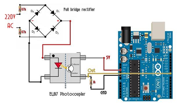
  1. The FET sits in that black box left hand side in your video?
  2. The GND lead of your generator is being connected to the "source" pin of the FET.

  • Liked by
  • Inception
Vidura posted this 20 June 2019

Hey Fighter, Please don't misunderstand my last post, I did not want to disregard anything of your work, as I stated my first impression was that it is AU. Take my comments for information purposes if you want, in some cases when we deal with small power levels all this things can be valuable, but if you could actually light two 35w bulbs, the influence from the SG can of course be neglected. Anyway here a suggestion for a very simple isolating switching application. Vidura

Vidura

  • Liked by
  • Inception
YoElMiCrO posted this 21 June 2019

Hi all.

@ Fighter.
I agree with what you mention.
Some time ago perform tests to contrast what N.E Zaev commented about his ferrocassor.
Your circuit and yours have the same in common, only not with bucking coils.
In order to appreciate the phenomenon, a nucleus with a large mass is necessary,
only a small part of it creates the BH/2 energy due to the automation trend
of the core.
The material you use is very good, it has a large μ(max)/μ(inc)] ratio.
To observe the energy gain, iL should be grown up to the value of μ(max) and it will depend on the core, but always around 1.2~1.5Hc, ie, within the reversible area of ​​hysteresis.
It can be shown that the energy absorbed by the charge from the source during the magnetization cycle is:
Edc^2/RL(Ton/T) for being parallel to the inductor, now ...
An energy is also stored in the inductor and will be 0.5iL^2L.
If we look at the behavior of the sling form at the time of Toff we will see an adiabatic process, this is due to the self-magnetization of the material used and contributes to the decrease of its internal entropy, this is where the free energy is.
Then for the demagnetization cycle or Toff we will have two types of energy, one is kinetic and the other potential, it is the sum of these energies that is delivered to the load.
If we analyze, we will see that Pin = [Edc^2/RL(Ton/T)] + [iL^2L/(2T)] and for Toff approximately ...
Pout = [Edc^2/RL(Ton/T)] + [0.5Edc^2/RL(td/T)] + [iL^2L/(2T)] if we assume Ploss = 0.
If the second member in the sums of the equation is different from 0, then Pout/Pin> 1 given that E(cd)=Ed+Efb.
We see that during the self-magnetization cycle the energy is really free and drifts
of the intrinsic property of temperature exchange with the middle of the ferromagnetic core, which from the engineering point of view can be approximated by an infinite heatsink.
To better understand the exposed ...

This study is by N.E Zaev as commented at the beginning of the post and a simple way to understand the phenomenon, without complicated equations or at least the minimum.

I hope I help you in the experiments.
Thanks for sharing.

YoElMiCrO

  • Liked by
  • Inception
Fighter posted this 21 June 2019

Guys, thank you for your posts, the information and idea from your posts are extremely interesting. Right now I'm at work and can't reply properly but I'll do it during the weekend for each of your posts. Sorry, if it would be possible to buy more time (to have like 30 hours per day) I would gladly do it... 🙂

@YoElMiCrO: I'm gonna read this document before asking some questions (even if I already have some in my mind right now about the content of your previous post):

Rediscovering Zaev’s ferro-kessor 

For example this, I find it very intriguing:

"If you want to find the secrets of the universe, think in terms of energy, frequency and vibration."
Nikola Tesla
  • Liked by
  • Inception
Close