Hi Fighter,
I have a possible suggestion for the premature death of your capacitor.
At switch mode PSUs the storage capacitors need to be specified for severe (1) pulsating currents - else they tend to explode. Standard electrolytic capacitors do not have sophisticated internal connections. So if pulsed with high repetetive currents they experience temperature rise. I experienced it live once when a SMPS exploded 8 capacitors one by one up to burning the machine it was supposed to feed.
Additionally SMPS require capacitors with (2) low inductivity of the leads (low ESR) in order to get the pulsating currents to the full surface of thecapacitor plates. Many electrolytic caps are specified for 50/60Hz only.
I suppose your huge capacitor was not specified for (1) nor (2). So this capacitor might be part of the tank circuit but not with full specified capacity but some intermediate parasitic R/L/C value.
Additionally the output capacitor inside your PSU might be as well part of the tank circuit. At such conditions the PSU is not able to measure currents reliably.
You might try using a diode in series to your 24V lead (coming from PSU) in order to eliminate backlash to your PSU.
-----------------------------
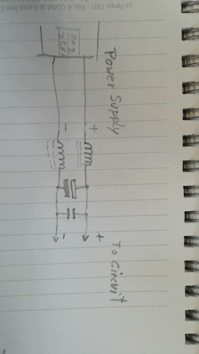
Your input configuration:
I feel that your setup operates intensively with the power supply as part of the oscillations.
Please be aware that a FET has an intrinsic, reverse and parasitic diode (not very fast) - see schematic symbol .
- In ON state the power will flow from plus to GND - as intended.
- IN OFF state the power might flow reverse through the parasitic diode.
YoElMiCrO suggested the insertion of an additional diode in order to overcome this implication.
---------------------
It would be very interesting if you could check if the sweet spot (frequency) of your setup depends on the value or make of this huge capacitor.
-------------------------
Fighter, you should not be disappointed. :-)
Unfortunately you tapped into several parasitic properties of electronic components. In fact EVERY component has R/L/C properties or some parasitic diodes .... but usually they do not matter if used in proved standard circuits. High frequency is one ingredient that makes them matter. That's life! Sometimes learning goes the hard way. But you will get support in this forum. Important is - you DO learn.
So, before you dive into opto couplers please re-check the operation of your setup:
- with those two diodes added (see above)
- Sweet spot (resonance) without and with different makes or values of capacitors (replacing that high 10000µF cap.)