Romanian ZPM (Zero Point Module)

  • Topic Is Locked
  • 3.4K Views
  • Last Post 12 February 2023
  • Topic Is Solved
Fighter posted this 07 February 2023

This is the imported thread (from the old aboveunity site) about my ZPM:

For references I will keep the original posting date for every imported post.

Note: This thread is public, everyone can see it, even the visitors which are not members here.

For the posts made by former aboveunity members which are not members on our site I'll use a member placeholder named UndisclosedMember.

Regards,

Fighter

"If you want to find the secrets of the universe, think in terms of energy, frequency and vibration."
Nikola Tesla
  • Liked by
  • Jagau
  • Inception
Atti posted this 30 July 2019

Hi.

The shape of the waveform is probably not inverted.

And?

He may have changed shape.

  • Liked by
  • Inception
  • AlteredUnity
cd_sharp posted this 30 July 2019

Hey, guys, that is assymetrical regauging, impossible to miss. One more confirmation, Fighter.

If you know how to build such a device and you're not sharing, you're a schmuck! - Graham Gunderson

  • Liked by
  • Inception
UndisclosedMember posted this 30 July 2019

nice one boys !!.  momentum is good!

checkout this bargain from china ( same core for half the price ).  https://www.alibaba.com/product-detail/Medium-frequency-transformer-amorphous-c-shaped_60531008579.html

il let you know if it pans out, - i have only made request thus far, - but will open my wallet if it pans out.

it appears too be an equivalent model, down too 2% error margin,. let me be the first too say woop woop

  • Liked by
  • Inception
Fighter posted this 30 July 2019

@UndisclosedMember, @Cd_Sharp: Thank you guys, still more research needs to be done but personally I feel like I started to see the light at the end of this long and difficult road... 🙂

@UndisclosedMember: If that core have the same characteristics like those produced by Hitachi Metals then the price is good. If you live in Europe then customs from your country will ask you to pay the VTA (so the cost will increase depending of the value of the VTA in your country), be prepared for that. 2% difference in dimensions doesn't really matter, my only concern is, talking about Chinese suppliers, if the characteristics are the same. No offense intended to Chinese people but it's a fact, if they took a "shortcut" in the production process to cut the costs/price there could be some differences. Hope everything will be okay, Patrick, crossed-fingers 🙂

"If you want to find the secrets of the universe, think in terms of energy, frequency and vibration."
Nikola Tesla
  • Liked by
  • Inception
Fighter posted this 30 July 2019

@Atti: What's the device producing that output waveform ? If you don't mind to provide some details, I'm just curious. Thanks.

"If you want to find the secrets of the universe, think in terms of energy, frequency and vibration."
Nikola Tesla
  • Liked by
  • Inception
Atti posted this 31 July 2019

Fighter and everyone.
I only try to study the effects.
Existing measurements do not always have to take out real events, but only the possibility of the effect-effect, its further use.
(You have to be very careful with the actual performance measurement! Measurement is always a guess for some quantity.)

There are cases (usually for the most part) where the transformer has the same operation as the motor generator.
The primary and secondary windings can be replaced in the same way. The switching time is also different, but the implementation is different.

In this section, we investigate how the shape of the signal and its potential effect on the input coil is affected by another voltage change.
- Here's the question:
- What are the facts that can cause a voltage change?
- How much current do you have?
-Can you get extra performance?
- To what extent does it affect my power supply?

This fact is the rotation of the permanent magnet at the motor.
The excitation of the voltage resulting from the rotation of the permanent magnet can be clearly seen in the oscillogram. In the case of a transformer, the associated output coils should be considered here. The timing of this (on and off) is also an important factor. But the primary on and off. The two on and off systems are now controlled as a single system. The use of a band should be pursued. The effect of load current change is clearly visible in this video.

- At the transformer, the associated output coils.
Timed switching of coils and its effects.Chris constantly refers to this.
The magnetic polarities are the same for both. The north is opposite the north polarity. Or vice versa.
Setting the time for both (motor generator or transformer) is very important.

A character Adams engine generator.

There is only one coil (primer) per iron column. Right and left.
The poles of the permanent magnet on the rotor are the same, N-N-N-N.
The coils are connected in series (N-N) and the measurement is made on only one coil. The load is diode-wound.
With proper timing, the rotor rotation speed will increase. Otherwise, it will slow down.

This is an older video.

it for short.

  • Liked by
  • Inception
UndisclosedMember posted this 01 August 2019

hei YoElMiCrO! - This looks significant - i just checked up on 'esperado' = waiting (time) and 'adiabatic' = transfer of [...] between 2 bodies without any heat transfer! {Adiabatic definition: (of a thermodynamic process) taking place without loss or gain of heat}

thanx 4 sharing this! 🙂


Visualize the Shape of Things Not Yet Seen with Eyes !! ... .. .

  • Liked by
  • Inception
UndisclosedMember posted this 02 August 2019

Gday Lads, - i have found there are several cores, similar too the one in question previously.

this is now the cheapest i have found, - i am ordering a few different models, - as i am of the belief that they should all work

along with many more common ferrite cores, - including many i already have, - but since they are large and cheap, its well worth a look.

UndisclosedMember, your last post with the scope shot, - this is the input set of bucking coils.,  with no output load coils connected ?

  • Liked by
  • Inception
Fighter posted this 02 August 2019

Hi guys,

I'm posting here one of UndisclosedMember' posts from Measurements thread as I find it very important for ZPM. Basically is a confirmation that there are currents going in both directions in that shunt resistor I used when trying to measure the input and the ZPM is actually sending power back to the DC source because it "sees" the DC source as a load and it's trying to power it up. This could explain DC source's "confusion" in readings as its made only to power up loads not to receive power back from the loads.

My Friends,

In the below image, we see two numbers with a red line above them:

Both numbers are very different! Average or Mean: 172mV and Vrms or Voltage Root Mean Square: 610mV.

Importantly, we have a DC Power Supply! Direct Current meaning one way only! At lease if one is running a Linear Load like a Light Globe!

All Current below the faint turquoise line I have drawn in here:

is Negative Current, its below the Zero Graticule Line of the Probe measuring it.

The Root Mean Square is 610mV across a 0.25 Ohm Resistor, this is approximately: 59.512 Watts input to the ZPM.

At the same time the Scope is saying we have 172mV across a 0.25 Ohm Resistor, this is approximately: 17.082 Watts input the ZPM.

Both figures cant be right! So in this case which one do we trust?

We know Power is coming back at us, the ZPM sees the Source as a Load! The ZPM is trying to Power its load, being the Power Supply.

So what do we have? What are the facts?

  1. 172mV across a 0.25 Ohm Resistor, 0.688 Amps, approximately: 17.082 Watts input the ZPM.
  2. 610mV across a 0.25 Ohm Resistor, 2.44 Amps, approximately: 59.512 Watts input to the ZPM.


NOTE: RMS is always positive, it does not give an indication of the direction of power.

Now, I ask others to correct me if I am wrong!

You should use Mean, which is an integration ( Addition ) of the instantaneous power readings ( each sampling point on your screen ) over as many Cycles you have on your screen, which is time, which yields total Energy for this time interval.

This is because your DUT is Non-Linear, and your Source is DC, the DUT sending Power back to Power the DC Source!

With a Linear Load, and an AC Source, you should use RMS most of the time.

"If you want to find the secrets of the universe, think in terms of energy, frequency and vibration."
Nikola Tesla
  • Liked by
  • Inception
UndisclosedMember posted this 02 August 2019

Hey Fighter,

This is correct! The RMS Values are including the Power being returned back to the Source and not giving you an indication of the Direction of Current.

Direct Current, is a unidirectional Current, its not supposed to Alternate over Time or it is then AC, Alternating Current.

E.G: The scope records: 0123456789876543210.

Now we Integrate ( Series addition ) : 0 + 1 + 2 + 3 + 4 + 5 + 6 + 7 + 8 + 9 + 8 + 7 + 6 + 5 + 4 + 3 + 2 + 1 + 0 = 81.

Now divide by the number of points recorded: 81 / 19 = ‭4.26315789.

‭4.26315789 is the average.

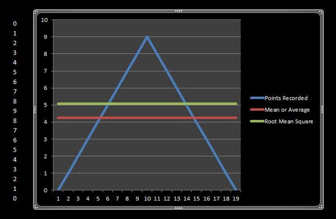
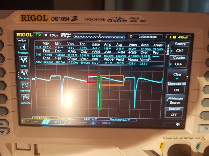
What does this mean? It means we can split the Triangle above the Mean line, down the middle, and put the two sides in the open area on the ends, the area is the same. This gives us a perfect Mean value. The shown RMS Value you can see is well above the mean height! There is no even distribution of the Waveform above the RMS value to the ends of the Wave shape. The area is not equal to the open area on the sides under the line!

The reason straight DC is so easy to measure is because its a straight line:

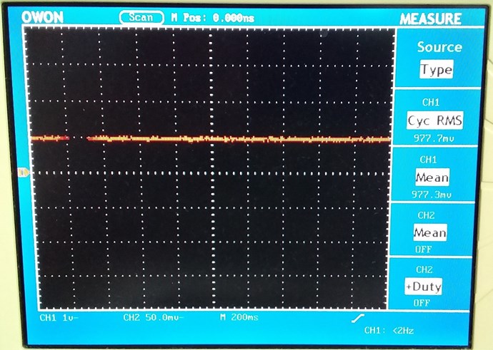
The area under the Straight Line, the Waveform is a Rectangular Box: H x W = Area. 977.7mV x 1t = 977.7mV

NOTE: The ZPM is a NON-Linear Load.

Now in the ZPM, if we use RMS, we cant include Power coming back as USED Power, which is what RMS power setting is doing! This is wrong!

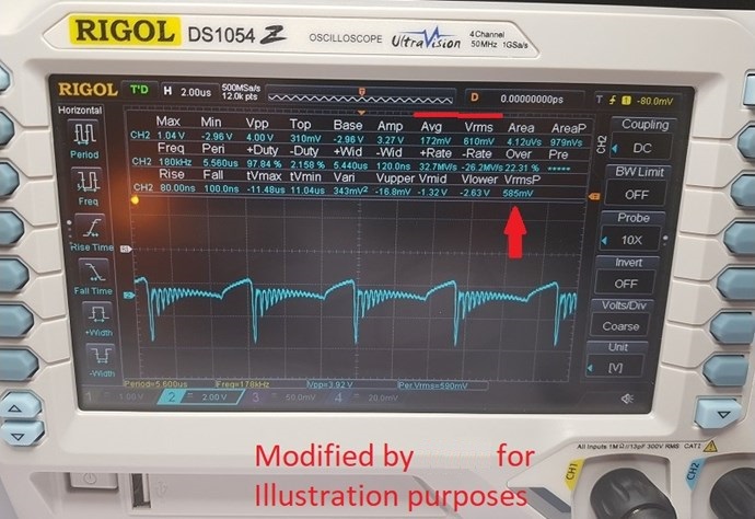
Also NOTE: RMS is fine for Linear Loads! It will measure almost the same as Mean! See Here.

RMS is Root Mean Square, the equation is fairly straight forward:

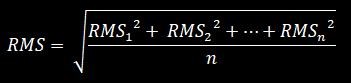
See www.electronics-tutorials.ws for much better information on all this.

So we could say:

int TotalPoints = 19;
double Integration = Math.Pow(0, 2) + Math.Pow(1, 2)
                   + Math.Pow(2, 2) + Math.Pow(3, 2)
                   + Math.Pow(4, 2) + Math.Pow(5, 2)
                   + Math.Pow(6, 2) + Math.Pow(7, 2)
                   + Math.Pow(8, 2) + Math.Pow(9, 2)
                   + Math.Pow(8, 2) + Math.Pow(7, 2)
                   + Math.Pow(6, 2) + Math.Pow(5, 2)
                   + Math.Pow(4, 2) + Math.Pow(3, 2)
                   + Math.Pow(2, 2) + Math.Pow(1, 2) + Math.Pow(0, 2);

double Average = Integration / TotalPoints;

MessageBox.Show("RMS: " + Math.Sqrt(Average));

RMS: 5.07314913098986

Note: a small difference: 5.07314913 RMS vs 4.26315789 Mean, the difference: ‭0.80999124‬. The values often vary a little between RMS and Mean, but with a Non-Linear-Load, Mean must be used.

Note: I have used the same numbers in this example, RMS Voltage and Mean Voltage readings on the scope can be different, so please be aware this example is only that, an example.

Note: (81 / 19)2 is not the same as squaring each number and adding.

Again, RMS does not give you an indication of the Direction of Power, the reading is always Positive, the Mean or Average setting is not this way! Mean can be Positive, Negative or Zero. Zero means all the Power you send Out to your Load  ( DUT ) You get the exact same back again! 1 + -1 = 0...

For some it may seem impossible, but Electromagnetic Induction really does work!

Now I am not perfect I make mistakes! So I urge you to all do your own research on this! Research how to measure the Area under a Curve (  Scope Waveform ) and find out more on this. I did post several very good videos on this!

Remember: Every pixel drawn on your scope screen, it is a Potential Value Recorded. Millions of values measured then recorded of that Potential over Time. All these values, in the Scope Buffer, indicate Instantaneous Power measured over time, this is the X Axis, the values themselves are the Y Axis, Amplitude.

P.S: a better code example if you want to play with this:

Integration = 0.0;

double[] Points = new double[] { 0.0, 1.0, 2.0, 3.0, 4.0, 5.0, 6.0, 7.0, 8.0, 9.0, 8.0, 7.0, 6.0, 5.0, 4.0, 3.0, 2.0, 1.0, 0.0 };

for (int i = 0; i < Points.Length; i++)
    Integration += Math.Pow((Points[i]), 2);

double Mean = Integration / Points.Length;

MessageBox.Show("RMS: " + Math.Sqrt(Mean));

  • Liked by
  • Inception
Close