Romanian ZPM (Zero Point Module)

  • Topic Is Locked
  • 3.3K Views
  • Last Post 12 February 2023
  • Topic Is Solved
Fighter posted this 07 February 2023

This is the imported thread (from the old aboveunity site) about my ZPM:

For references I will keep the original posting date for every imported post.

Note: This thread is public, everyone can see it, even the visitors which are not members here.

For the posts made by former aboveunity members which are not members on our site I'll use a member placeholder named UndisclosedMember.

Regards,

Fighter

"If you want to find the secrets of the universe, think in terms of energy, frequency and vibration."
Nikola Tesla
  • Liked by
  • Jagau
  • Inception
Fighter posted this 28 July 2019

Hi UndisclosedMember,

Thank you and welcome to our community. Are you making research ? If yes here you can share your experiments and results.

Related to approximation of power using light-bulbs, in this case is not only the luminosity, there is real power on output, if I connect the light-bulbs using wires with lower diameter (AWG) the wires becomes so hot that their plastic enclosure is starting to melt. All my wires are multifilar so it's not the high-frequency making them hot (as could happen with solid wires because of the so called skin-effect).

The DC source's output is DC of course, it's not high-frequency pulsed, that's the job of the MOSFET driver receiving signal from the signal generator; on DC source's output I used also a filter made from a fast Schottky diode on the positive output and a big 10,000uF/60V electrolytic capacitor to protect the DC source against possible noise coming back from MOSFET driver but the source's readings remain the same.

In one of my previous posts (made 19 hours ago) I measured input using more current-sensing resistors, what's curious about measurements it's the fact that I cannot detect the direction of the current: Vrms is always positive no matter how I put oscilloscope's probe on those resistors; seems to me that the DC source is powering the ZPM but in the same time the ZPM is sending power back to the source. As you can see in that post, through the current-sensing resistors there seems to be currents going in both directions.

Have a nice evening too.

"If you want to find the secrets of the universe, think in terms of energy, frequency and vibration."
Nikola Tesla
  • Liked by
  • Inception
Vidura posted this 28 July 2019

Hey Fighter, thanks for sharing your work, I have noted that you could bring down the frequency to around 100kHz, and a smaller duty cycle. This is certainly can advantage for the switch, as it will run cooler. If I may, for testing the gate waveform the scope ground should be connected to the source of the MOSFET,.As there is different probe ground needed for the output signal you have to test the signals separately. Anyway your scope shots show a reversal in the output polarity at the moment of switching off. Also a ringing is present which seems to produce a pulstrain. Regarding the voltage it is likely that the transistor is at the limit of its capabilities, or even avalanching already. If the pulses are short the device might support values above the maximum rated, but could be stressed and failure prematurely. You could try with an alternative with higher voltage rating. Regards Vidura.

Vidura

  • Liked by
  • Inception
Fighter posted this 28 July 2019

@Vidura, you're welcome, that's why I'm here to share my work and also to learn. And you're right, my previous measurements are wrong, after I removed that broken MOSFET from driver I designed the measurement scheme wrong then I just followed the scheme.

I just did the measurements again and I'm gonna post the info below.

Thanks for the idea about duty-cycle and frequency, I'll try another combination of these parameters to lower down the temperature in the MOSFET driver's radiator 'cause right now I can run tests for about 5-7 minutes before needing to shotdown and let that radiator to cool down. I was already thinking to put an 12V cooler inside the box, I already have a constant voltage source inside powering the LED indicator. Nice idea, thanks !

@UndisclosedMember, please disregard the measurements section from my previous post, I'm adding updated measurements below.

So I connected the yellow probe to the MOSFET: probe's ground to the source and the probe itself to the gate:

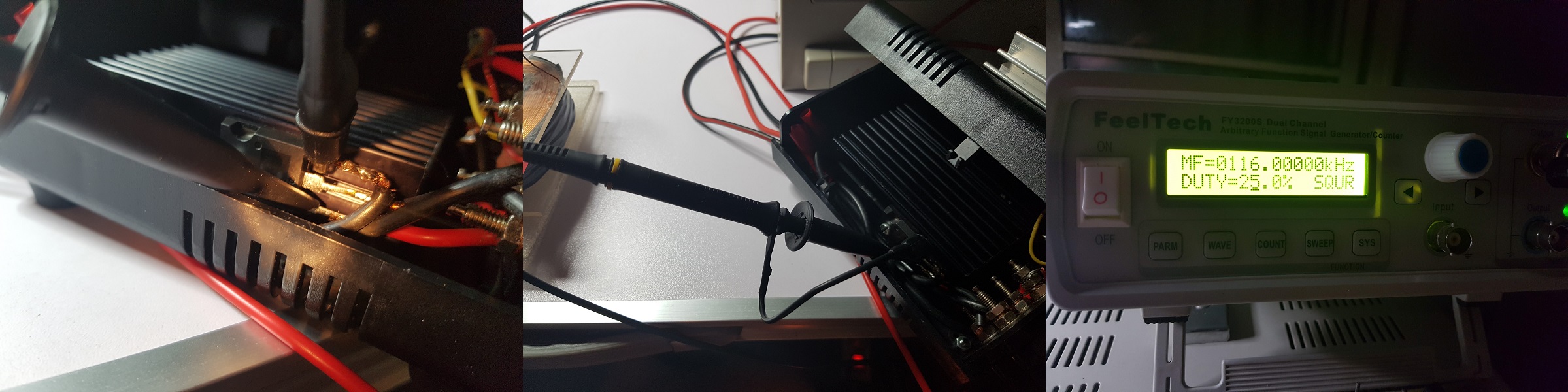
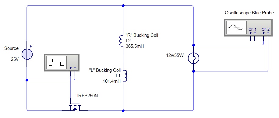
This measurement's schema is the following:

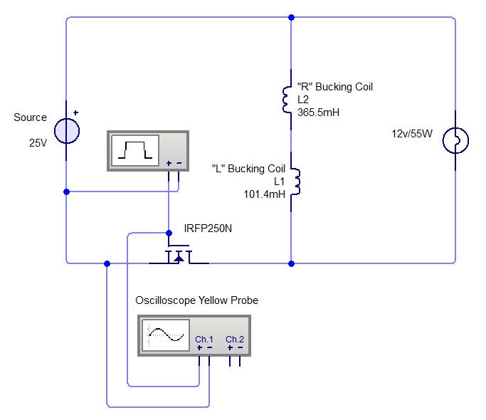
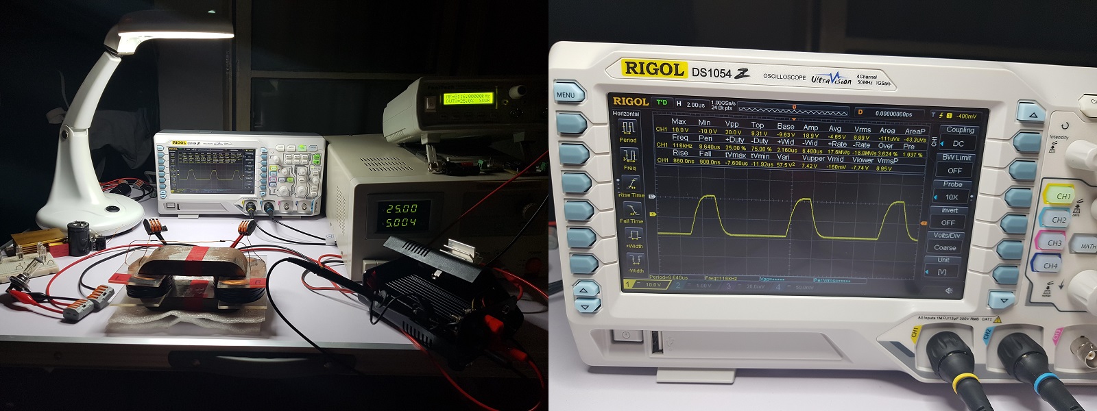
The MOSFET driver's switch is off so ZPM is not powered but the signal generator is on and is already sending signal to the MOSFET which is shown by the oscilloscope:

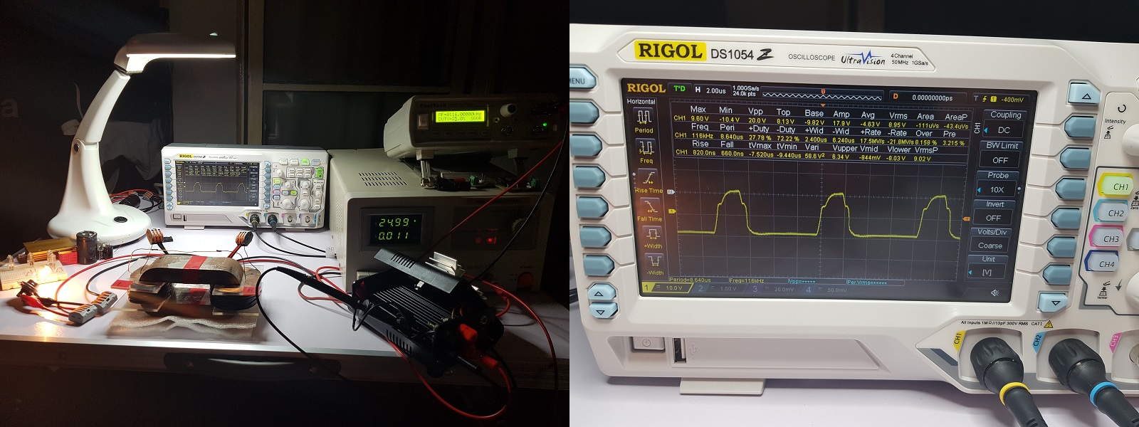
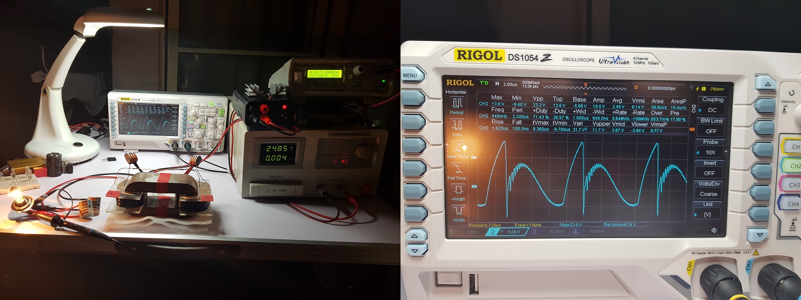
Then after turning MOSFET driver's switch on the ZPM is powered on and the readings from the MOSFET are in the next image:

Then I disconnected the yellow probe then moved on to measure the output again: I connected the blue probe to the output, more specific to the light-bulb's pins:

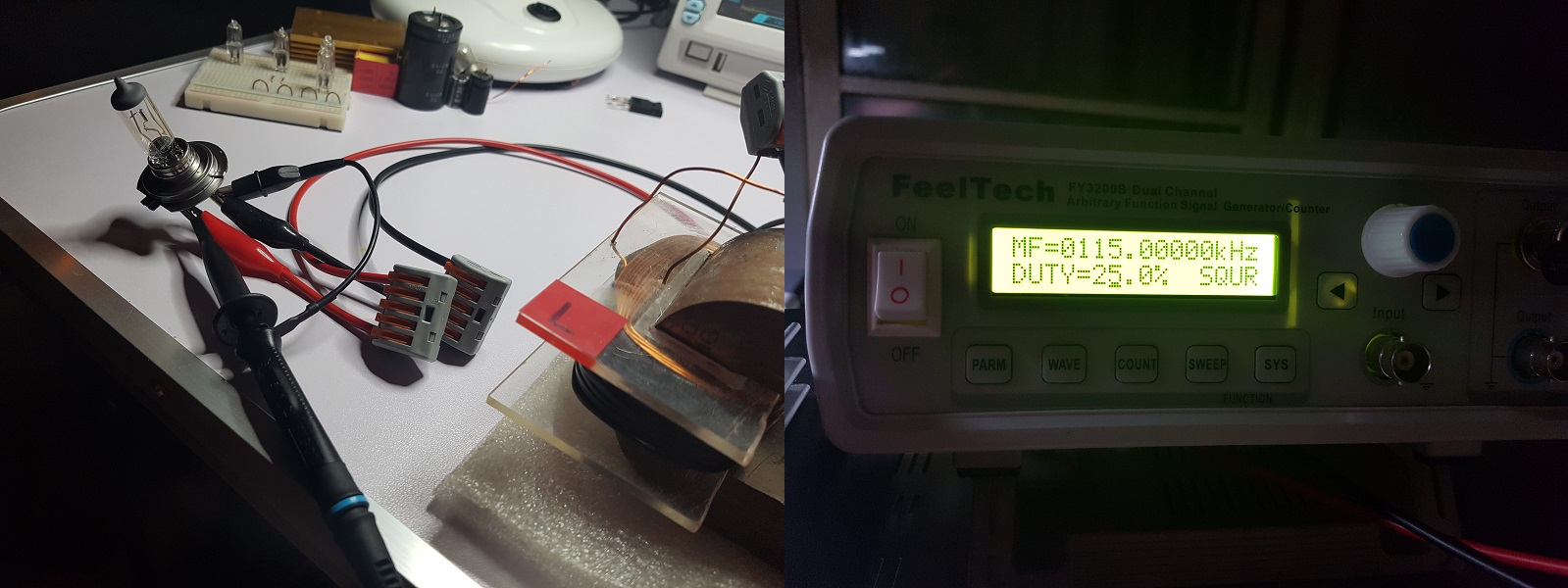
This is the schema of the output measurement:

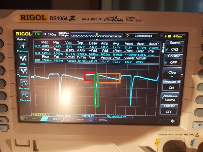
And this is the output measurement, it's the same as I posted it last night - looking like Graham Gunderson's device output:

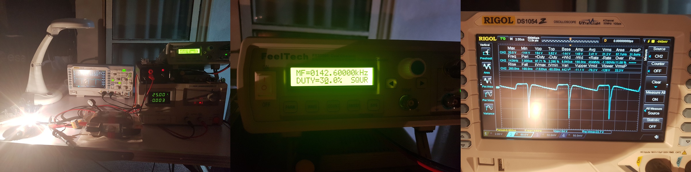
And also for later references I'm putting here again the identical output measurement I've made yesterday but made with a 12V/5W light-bulb on output - notice the Vpp = 164V:

"If you want to find the secrets of the universe, think in terms of energy, frequency and vibration."
Nikola Tesla
  • Liked by
  • Inception
Jagau posted this 29 July 2019

Very interesting experiment

Jagau

  • Liked by
  • Inception
UndisclosedMember posted this 29 July 2019

i have a question...  can you link me too that metglass core ?. i think i want too back you fighter with a replication

there is a few around but i mayaswell get the same size and model

my replication of this in the mrpreva thread worked ok, but not this well. - i was using a flyback core

i have been trying the last week too make it happen with different circuits, - both h bridge and only positive offset's .  but ultimatley i cannot get the core into magnetic resonance even with correction capacitors, - iron is going too take some work, or, perhaps delayed conduction manually., - but i dont quite know how too go about it , even though i suspect i have the tools on hand too maniuplate the waves ;-0)

  • Liked by
  • Inception
Jagau posted this 29 July 2019

Hi fighter


if you are looking for a high performance optocoupler up to 2 MHZ
go with the 6N36 and 6nN36 according to your needs.


For your first question:

Maybe it works by using ferrite cores and using much lower frequencies, I'm just describing what I'm using in my research now.

Yes it works very well with a ferrite, to have tried it some time ago.


For your results it seems that one approaches both.

We are on right track

Sorry not to see answered before I was very busy


Jagau

  • Liked by
  • Inception
Fighter posted this 29 July 2019

@Patrick, sure, it's produced by Hitachi Metals but I bought it from Poland, this is the link to the site:

https://www.dacpol.eu/en/cores-amorphous-53825/product/hitachi-cores-made-form-amorphous-metglas-materials#sklep

In that page if you click "Check ?" button for a specific core it will show to you how many pieces they have in stock (right now I see they have 238 AMCC-200 cores). Also at the top of the page (near "Net price in" text) you can change the currency from Polish currency to EUR or USD so you can check the prices in these currencies.

My model is AMCC-200, this is a photo I took when I received it:

But depending on your location maybe you may find it in other places closer to you, I chosen Poland because it's a neighbor country of Romania.

About dimensions, here is a draft I've made for CNC when I ordered the pieces for the coils supports, you can see the exact dimensions at the top of the page:

And here are links to my files about Metglas technical specs:

Hitachi - AMCC Cores Technical

Hitachi - AMCC Cores Presentation

I'm just guessing here but I think the problem with pure iron cores is that they tend to remain magnetized for a while even if the coil is not producing magnetic field anymore, it's the normal behavior of any iron object. So the magnetic field is not collapsing too fast after the coil is disconnected from power.

On the other side Metglas even if it's still containing iron too when the coil is interrupted the magnetic field in the core is collapsing faster, that's one of the advantages of this type of (amorphous alloy) cores. But you can check the characteristics of Metglas cores in those technical documents I posted here.

"If you want to find the secrets of the universe, think in terms of energy, frequency and vibration."
Nikola Tesla
  • Liked by
  • Inception
Fighter posted this 29 July 2019

@Jagau, no worries; interesting, thank you for the info I'm gonna check these optocouplers and where I can find them to buy.

So this would work with ferrite too, it's good to know as it would significantly drop the building costs of this kind of device.

Thank you.

"If you want to find the secrets of the universe, think in terms of energy, frequency and vibration."
Nikola Tesla
  • Liked by
  • Inception
YoElMiCrO posted this 29 July 2019

Hi all.

@Fighter. After performing numerous tests I think I understand the reason why the phenomenon is created. In a few days I will publish what I have seen, so we can all contrast whether it is real or fictitious.

Thank you all in advance.

  • Liked by
  • Inception
UndisclosedMember posted this 30 July 2019

My Friends,

There are three things here that need attention:


  • Red: Input Pulse, On Time.
  • Green: Inductive Collapse.
  • Orange: The Sawtooth Waveform we are seeking, another pumping phase on the Output otherwise not present.
     

Keep up the excellent work Fighter!

  • Liked by
  • Inception
  • AlteredUnity
Close