Fighter's ZPM (Zero Point Module) failed replication by Itsu

  • 8.1K Views
  • Last Post 18 December 2022
Itsu posted this 07 November 2022

Hello all,

i opened this thread to discuss my replication of Fighter's ZPE (Zero Point Module).

I already opened a similar thread on OUR.com (https://www.overunityresearch.com/index.php?topic=4374.msg101654#msg101654 ), but will transfer some data from there to here.

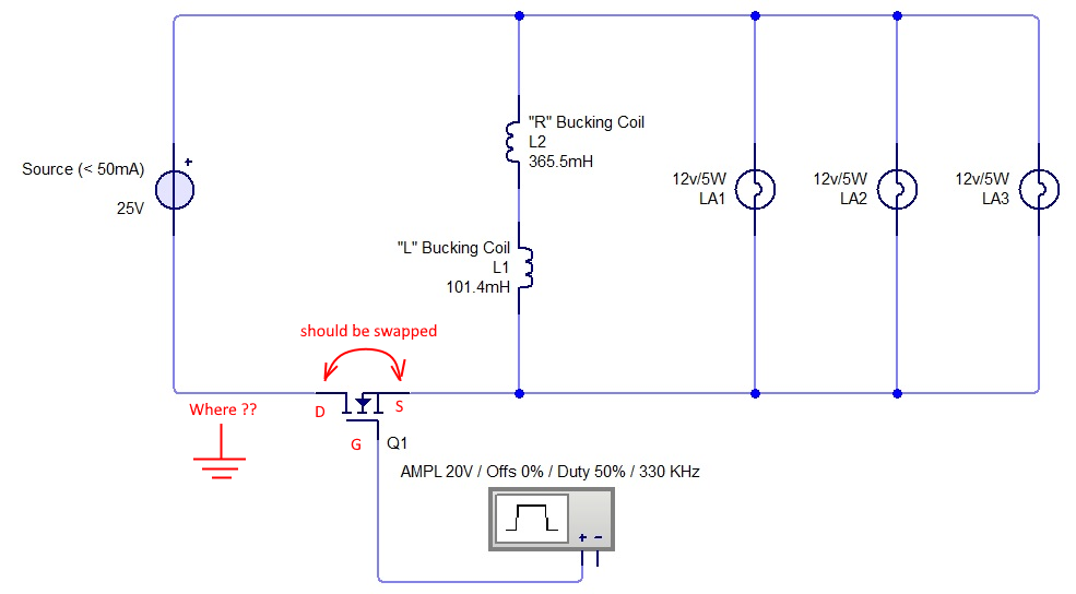
Initially i understood that the below diagram was correct and complete, but it turns out its not.
There is a ground connection somewhere, but i am not sure where it is exactly, hopefully someone can tell me.
The MOSFET is shown wrong as the Drain and Source should be swapped, which was corrected later in Fighter his thread so therefor the mentioning in red.

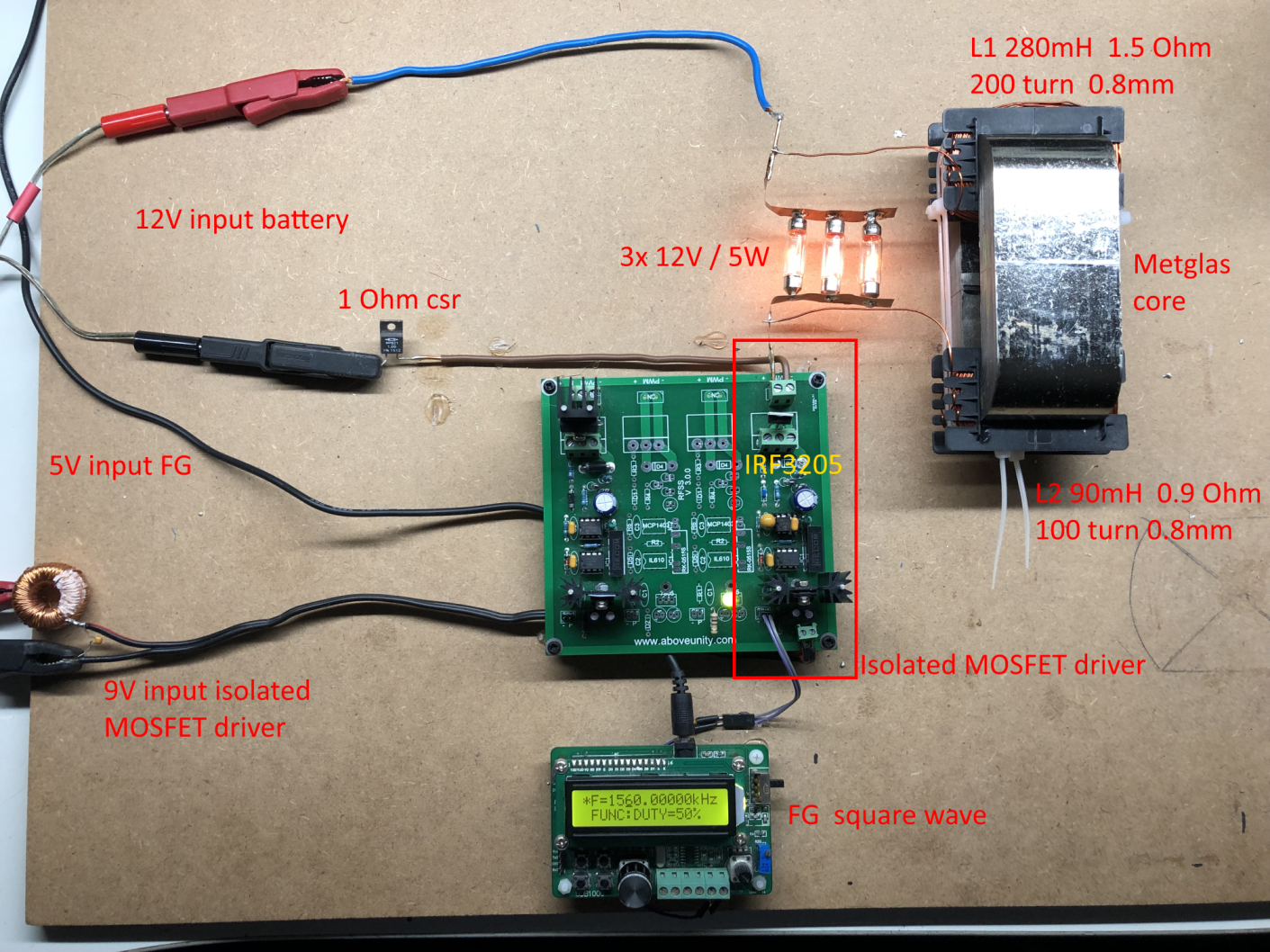
I have build up a similar circuit and the data is shown here: 
(Be aware that the induction measurement was done at 10kHz, but due to the influence of the metglas core it can be (and is) completly different on other frequencies, see my thread on OUR.com for a VNA scan of the coil/core)


I am using a 12V battery for now as my PS (minus NOT grounded) was acting weird due to all the pulses coming back from the ZPE device.
Up till now no special effects or resonance in a 0 to 5MHz range are seen with this setup, but as said the grounding may be the problem here.

Itsu
Order By: Standard | Newest | Votes
Itsu posted this 07 November 2022

Hello all,

i opened this thread to discuss my replication of Fighter's ZPE (Zero Point Module).

I already opened a similar thread on OUR.com (https://www.overunityresearch.com/index.php?topic=4374.msg101654#msg101654 ), but will transfer some data from there to here.

Initially i understood that the below diagram was correct and complete, but it turns out its not.
There is a ground connection somewhere, but i am not sure where it is exactly, hopefully someone can tell me.
The MOSFET is shown wrong as the Drain and Source should be swapped, which was corrected later in Fighter his thread so therefor the mentioning in red.

I have build up a similar circuit and the data is shown here: 
(Be aware that the induction measurement was done at 10kHz, but due to the influence of the metglas core it can be (and is) completly different on other frequencies, see my thread on OUR.com for a VNA scan of the coil/core)


I am using a 12V battery for now as my PS (minus NOT grounded) was acting weird due to all the pulses coming back from the ZPE device.
Up till now no special effects or resonance in a 0 to 5MHz range are seen with this setup, but as said the grounding may be the problem here.

Itsu
Itsu posted this 08 November 2022


After reading the by me accessible threads and my own experiments, i think i can name the below facts.
Please correct me if wrong, but please present some data to show what is wrong.

# Fighter shows us his effect as being 2 or more 12V bulbs nearly fully lit when the ZPM is at resonance causing the DC source input current meter decreases to near 0mA.
See this post video around the 3:50 min mark:  https://www.aboveunity.com/thread/romanian-zpm-zero-point-module/?order=all#comment-4b4524d9-81b1-4605-b930-aa71010a436b

# No one replicating this ZPM was able to show the same effect meaning: 2 or more 12V bulbs nearly fully lit when the ZPM is at resonance causing the DC source input current meter decreases to near 0mA.

# No one replicating this ZPM besides me has the coils in the same spot as Fighter meaning at the short part of the cores (not sure this is crucial).

# Replicators using a battery as input do not report seeing any resonance in their ZPM.

# low pass input filters in a DC source can cause a resonance as seen in the ZPM.

# a ground connection on the negative lead of the DC source is needed to have resonance in the ZPM together with any filtering in the DC source.

  
Please comment,   regards Itsu
 

Itsu posted this 07 November 2022

I understand from Fighter that his PS minus lead is connected to chassis ground and thus earth ground.

My severall PS's all have NO connection from their minus leads to chassis ground / earth ground.

Are there more members having a PS which has its minus lead connected to chassis / earth ground?

Thanks Itsu

editor posted this 07 November 2022

Hi Itsu, 


My PS has minus terminal and ground chassis / eart ground connected.


brd

Itsu posted this 07 November 2022


Thanks editor and YoElMiCrO,

good to know, i must then have 3 different lab PS's which have their minus / negative lead NOT connected to ground.

So i can place the ground point in the above diagram on the PS minus / negative connection.

I understand from the Fighter thread that there must be a ground connection for the "effect" to show up, so i will ground my battery minus lead and retest.

Itsu

Itsu posted this 07 November 2022

A new sweep from 0 to 5MHz now with the earth ground connected to the minus lead of the battery does not show any resonance or decrease of current effect.

Using a similar PS (Manson SPS9400) as shown by Chris in his thread (0-15V @ 40A) which has its minus lead NOT connected to ground does show some resonance around 62kHz but only when connecting an earth ground to the minus lead which confirms the need for a grounded minus lead.

But no decrease of the input current is noted during this resonanse and the bulbs (2x 12V / 21W) stay on normally.

Itsu 


Itsu posted this 15 November 2022


I made an overview video to show how my setup is right now after having tried severall other setups like different bulbs (21W bulbs) and severall (5) other power sources.

I did notice some resonance points, but all at different frequencies depending on the power source (or external filter) in use, so i think these resonances are mainly influenced by the used filtering in the used power supplies.
The battery (12V) did not show any resonance points across a 0 to 5MHz frequency range.

We have opposing magnetic fields as shown by the "Pole Detector" app (thanks Editor). 

Input power as shown by the scope never exeeds the power consumed by the 3x 5W parallel (15W) bulbs, so no need for accurate input / output measurements as i did in my thread on OUR.com.

So i am kind of out of options to find the anomaly shown by Fighter in his setup.

There are some things to try like removing the tension (currently 2 tiewraps) which holds the 2 core halfs together, or removing the isolation between the FG and MOSFET and/or attach the input voltage to the MOSFET driver to the same (oscillating / resonating) PS as the main circuit (now different PS's), but i think those are far fetched.

Anyway, overview video here:

Still suggestions are welcome.

Regards Itsu   

Itsu posted this 21 November 2022

Fighter,

Thanks for the info on the isolated switching board from Vidura, looking nice šŸ‘

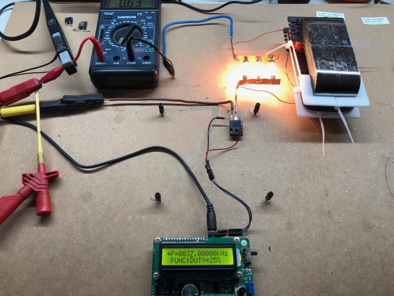
I have removed my isolating switching board, and put in an IRFP260N MOSFET directly on the SG/FG, see picture.
The circuit still behaves as normal here, so no dipping current when in resonance and the MOSFET get somewhat warm (60 degrees C) without heatsink.

the METGLAS core i bought it some years ago on Alibaba, but there is not much details to be found now. Could be poor quality.


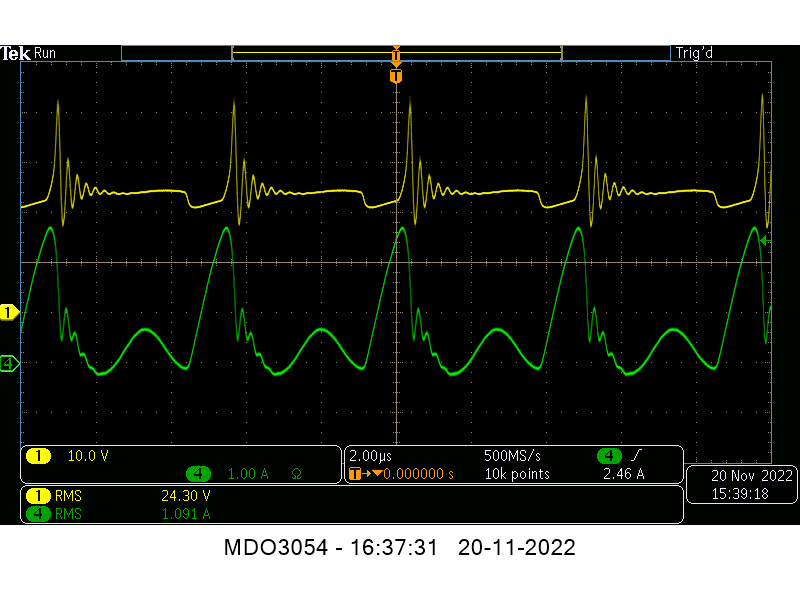
Screenshot taken below is from input voltage (yellow) and input current (green) when in some kind of resonance at 213kHz:


I can send you my core with coils as it is now, so if interested, please PM me with your address.

Regards Itsu

Itsu posted this 21 November 2022


Fighter,


No, there are no stamped labels on the cores, just some green stripes across the gap at one side indicating how they should be put together.
The company who made it was:  Anhui Lizhi Magnetic Material Co., Ltd in China.


Yes, i guess i will buy an AMCC 200 or 320 from mouser, because those are the ones used on the Bearden and Naudin setups.

 
I understand about your lack of time,  life has to be priority one, hobby or passion second.

Itsu

Itsu posted this 23 November 2022


YoElMiCrO

thanks for your insights, it seems you have it nicely figured out and presented clearly šŸ‘

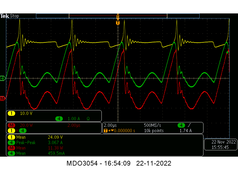
If we apply your formulas to my situation we have this screenshot there: 


Yellow input voltage 24V
green input current 
red math function yellow * green = input power
we see little current going back into the DC source and we have following data:

Rcu is 0.9 + 1.5 = 2.4 Ohm,
Rds (on) = 0.055 Ohm (IRFP260N)
Edc = 24V
Freq. 213kHz / T = 4.7us
Duty cycle = 25%   Ton = 1.175us

thus according to your formulas we have:

Ip = Edc/(Rcu + Rds (on))
Ip = 24/2.455 = 9.77A

and:

Pp = Edc*Ip
Pp = 24*9.77 = 235W

Pavg = Pp*(Ton/T)
Pavg = 235*(1.175/4.7) = 58.7W

But as can be seen in the screenshot, the Ip is much less (3A), and thus Pavg (11.38W)
This Pavg is so low that my MOSFET is barely heating up without heatsink.

So i wonder where the difference comes from between your calculations, my results and Fighters results.


Regards Itsu

Itsu posted this 24 November 2022

YoElMiCrO

thanks for the information, so you have a lot of experience under your belt, very good and very needed.


But what about my questions above, is there any chance your are able to answer those together with Fighter?

I know you need some data from Fighter and that Fighter is very busy right now, but perhaps some data is already available to make those calculations.
It could show the reason for his MOSFET heating up and perhaps explain some other things like if the core saturates and when.

But all in your and Fighters own time of course.

Itsu

Close