Romanian ZPM (Zero Point Module)

  • Topic Is Locked
  • 4.2K Views
  • Last Post 12 February 2023
  • Topic Is Solved
Fighter posted this 07 February 2023

This is the imported thread (from the old aboveunity site) about my ZPM:

For references I will keep the original posting date for every imported post.

Note: This thread is public, everyone can see it, even the visitors which are not members here.

For the posts made by former aboveunity members which are not members on our site I'll use a member placeholder named UndisclosedMember.

Regards,

Fighter

"If you want to find the secrets of the universe, think in terms of energy, frequency and vibration."
Nikola Tesla
  • Liked by
  • Jagau
  • Inception
cd_sharp posted this 21 June 2019

Vidura, my friend, I also tried to tune the device using a ferrite core. I had no luck either. I know that the magnetic field distributes homogeneously in ferrite. This could be related.

If you know how to build such a device and you're not sharing, you're a schmuck! - Graham Gunderson

  • Liked by
  • Inception
Vidura posted this 22 June 2019

Hey CD,
I honestly could not dedicate much time these days to the experiments, anyway I found some interesting effects. It is certainly worth to study more about this simple circuit. I dont have much varieties of cores , and there is no local supplier for metglas cores, so I simply used what I had at hand. There seems to build up a huge amount of recirculating- reactive power when resonant, and it happened very seldom that the bulbs lit, although that the power from the source should be present anytime. The voltage on the center tap between the coils becomes pretty high, and the two coils are always 180ª out of phase. Also I noted a important power drawing of the driver  >2w @ 450kHz , using a IRF250 mosfet, it could be normal, I didn't make the calculation. When I lowered the frequency  below 70 kHz the lamps(2x3W @6v) lit dimly at a lower harmonic . I guess the core and coils I used dont have  the adecuate parameters for a successful replication.

Then I wanted to share this  idea regarding the output power measurement. I remembered the researcher Robert Adams, who used to be a professional in calorimetric power measurements. It would be a possibility to use a small  submergible water heater of convenient  resistance (there are 12v models available), and take temperature readings for a exact amount of water, in a measured time interval the power / work can exactly be calculated. A very interesting comparison could be made with the change of temperature of the core, in the same time interval, in order to proof or disprove the theory of conversion of thermal energy in the core.

Vidura

Vidura

  • Liked by
  • Inception
Fighter posted this 23 June 2019

My friends, this can be feed-back looped as suggested. A cap is fed by the input power but also by one POC at a time like here , here and probably some other places.

I agree but first we should figure out what exactly from that output burned the 10,000uF/50V capacitor from one of the two channels of my bridge-rectifier using fast Schottky diodes and resolve that problem. Right now I'm sure it will happen again with the other channel if I try again. Also I have other 2 capacitors like this but they could be killed too if using them both in the same time on output will not resolve the problem šŸ™‚

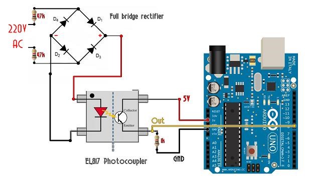
Fighter, this is how an optocoupler works, for example if wanting to insert the mains AC sine wave into a microcontroller. The AC signal is rectified (but not filtered) and fed to the optocoupler:

Between Out and Gnd is the optically coupled (electrically decoupled) signal. It's a very simple and useful little device.

Few questions about the capabilities of octocuplers:

  1. Are they "copying" exactly the form of the signal from a function generator ? Any kind of signal like sinewave, rectangular, triangular etc. with their duty-cycle ?
  2. How many Ampers can they handle ? Do they need radiators for high current ? I suppose they do.
  3. How much they can handle in terms of high-frequency ? Can they go to let's say 700-800 KHz ?
  4. What model would be able to handle currents of max. 5A and frequencies of max. 700-800 Khz (higher = better) without distorting the "copied" signal ?

"If you want to find the secrets of the universe, think in terms of energy, frequency and vibration."
Nikola Tesla
Fighter posted this 23 June 2019

In order to avoid endless discussions about your setup I suggest to feed it for about 5 hours from two or three 9V blocks being connected in series.

I tried to test it this way using 3 x 9V Duracell batteries (the nearby store don't have Energizer) but there is a flaw in this scenario: the batteries cannot sustain the same voltage during the tests. More specific this is what I did:

Searched for the optimum frequency of ZPM for 27V and saved it in the signal generator memory:

Then replaced the source with batteries. The luminosity of the light bulb is much lower and it stays on for about 15 minutes before it goes off. Batteries are getting warm. If I shutdown the test and wait for a while this can be repeated for another approx. 15 minutes:

After few tests like this wanted to check what's going on. I connected the multimeter, checked and found out that the voltage of the batteries drop fast from the beginning of the test, this is a video made after few tests:

As you can see the voltage is decreasing fast and after few tests batteries have only 23V not 27V for which I set the frequency of the test.

I kind of find this test inconclusive because having a variable voltage the frequency of the ZPM is not optimum at all so of course it will require more current all the time not just a few miliampers like it's happening when the source is providing the same voltage and there is a fixed optimum frequency.

Maybe I should search for an standard AC adapter providing around 25V, capable to provide a limited amount of current (to see if it's capable to power the test) and put an AC wattmeter on it during the test so I can check the input without the DC source. But I don't know if a standard AC wattmeter is capable of showing accurate reading at miliampers level...

Please continue your good work. I am willing to support you in terms of simple but effective methods of measurements for crystal clear clarity on your setup. Remember i.e. my recent post regarding measurement of luminositiy. So please ask!

Thank you, I will.

For utmost clarity please confirm:

  1. The FET sits in that black box left hand side in your video?
  2. The GND lead of your generator is being connected to the "source" pin of the FET.
  1. Yes. Actually I have two IRF3205ZPBF FETs because the driver has two channels but currently I'm using only one channel like in the photos I previously posted;
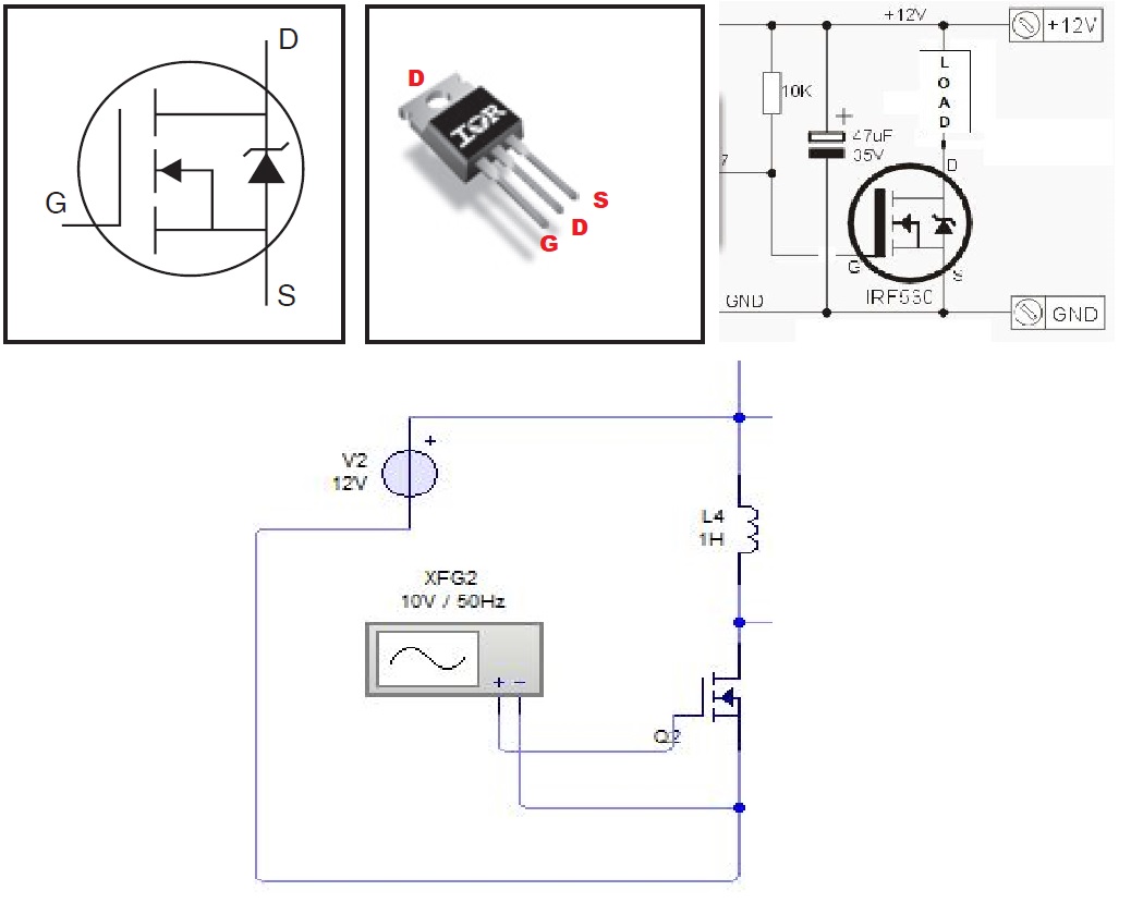
  2. Yes. Every FET is connected to a single channel from signal generator but I'm actually using only one channel from signal generator for ZPM; FET is connected as in this image:

If you want I could open that box to take some photos but I don't have a lot of time now, I need to answer to all the latest posts here as I promised.

"If you want to find the secrets of the universe, think in terms of energy, frequency and vibration."
Nikola Tesla
  • Liked by
  • Inception
Vidura posted this 23 June 2019

Hey Fighter, Thanks for sharing your work. I will answer your questions about optical isolating of the signal. But in first place I would suggest that you put a scope probe on the gate of the MOSFET, to check what signal is actually fed. What MOSFET you are using? optocouplers do only transfer signals, not power, and the frequency capability depends on the model. You have to be aware that the gate drive of a MOSFET require power, and this power increase proportional to the frequency. For this reason for practical implementation the frequency should better be kept lower. In the modul that I have shown in the video the power for this can be provided by the same supply, or by a dedicated separate source. And the driver is have a high speed optocoupler in the same chip integrated, for easy implementation. I can provide you a further simplified circuit if you want. Regards the back looping u would suggest to try with UF diodes rated for higher voltage, and a smaller capacitor, and some 100 nF Cap in parallel to smoot the spikes. Regards Vidura.

Vidura

  • Liked by
  • Inception
Fighter posted this 23 June 2019

@Vidura:

Hey Fighter, Please don't misunderstand my last post, I did not want to disregard anything of your work, as I stated my first impression was that it is AU. Take my comments for information purposes if you want, in some cases when we deal with small power levels all this things can be valuable, but if you could actually light two 35w bulbs, the influence from the SG can of course be neglected. Anyway here a suggestion for a very simple isolating switching application. Vidura

Hey, man, no worries, we're working with different devices having different behaviors here so any opinion is most than welcomed šŸ™‚ Especially because I'm a beginner in electronics I'm always listening and learning.

About the driver I saw the video so should I use in the same time the optocuplers and the IRF3205ZPBFs I already have ? What optocuplers should I use for these transistors ? How would the schema for a signle-channel driver would look like ? Could it handle high frequencies like 700-800 KHz ? Thanks !

Hey CD,
I honestly could not dedicate much time these days to the experiments, anyway I found some interesting effects. It is certainly worth to study more about this simple circuit. I dont have much varieties of cores , and there is no local supplier for metglas cores, so I simply used what I had at hand. There seems to build up a huge amount of recirculating- reactive power when resonant, and it happened very seldom that the bulbs lit, although that the power from the source should be present anytime. The voltage on the center tap between the coils becomes pretty high, and the two coils are always 180ª out of phase. Also I noted a important power drawing of the driver  >2w @ 450kHz , using a IRF250 mosfet, it could be normal, I didn't make the calculation. When I lowered the frequency  below 70 kHz the lamps(2x3W @6v) lit dimly at a lower harmonic . I guess the core and coils I used dont have  the adecuate parameters for a successful replication.

Then I wanted to share this  idea regarding the output power measurement. I remembered the researcher Robert Adams, who used to be a professional in calorimetric power measurements. It would be a possibility to use a small  submergible water heater of convenient  resistance (there are 12v models available), and take temperature readings for a exact amount of water, in a measured time interval the power / work can exactly be calculated. A very interesting comparison could be made with the change of temperature of the core, in the same time interval, in order to proof or disprove the theory of conversion of thermal energy in the core.

Vidura

So you saw almost the same behavior I presented here when the frequency is optimum but not low-amperage on your DC source's readings ? Could be something wrong with my source's reading and in the same time with the wattmeter's readings ?..

About reading watter temperature method, kind of need to buy anything because I don't have that 12V water heater and also I would need a waterproof temperature reader. I have a temperature reader on one of my multimeters but it's not waterproof and I never used it, don't know if it's accurate or not. Eventually I could use it to check if the temperature of the core drops, hopefully it can show me somehow accurate data...

Hey Fighter, Thanks for sharing your work. I will answer your questions about optical isolating of the signal. But in first place I would suggest that you put a scope probe on the gate of the MOSFET, to check what signal is actually fed. What MOSFET you are using? optocouplers do only transfer signals, not power, and the frequency capability depends on the model. You have to be aware that the gate drive of a MOSFET require power, and this power increase proportional to the frequency. For this reason for practical implementation the frequency should better be kept lower. In the modul that I have shown in the video the power for this can be provided by the same supply, or by a dedicated separate source. And the driver is have a high speed optocoupler in the same chip integrated, for easy implementation. I can provide you a further simplified circuit if you want. Regards the back looping u would suggest to try with UF diodes rated for higher voltage, and a smaller capacitor, and some 100 nF Cap in parallel to smoot the spikes. Regards Vidura.

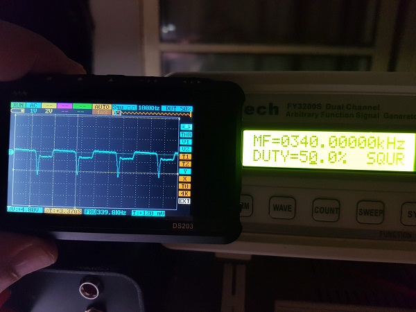
I'm using IRF3205ZPBFs on every channel, the driver has two channels but I'm currently using only one for this experiment. I disconnected the channel from ZPM and I put the oscilloscope on it, this is how it looks like, don't look like a very accurate squarewave but could be because of the high frequency:
About the driver I saw the video so should I use in the same time the optocuplers and the IRF3205ZPBFs I already have ? What optocuplers should I use for these transistors ? How would the schema for a signle-channel driver would look like ? Could it handle high frequencies like 700-800 KHz ? Thanks !

"If you want to find the secrets of the universe, think in terms of energy, frequency and vibration."
Nikola Tesla
  • Liked by
  • Inception
YoElMiCrO posted this 23 June 2019

@ Fighter.
Thanks for sharing your experiments.
What is happening to you may be buspumping, if that is
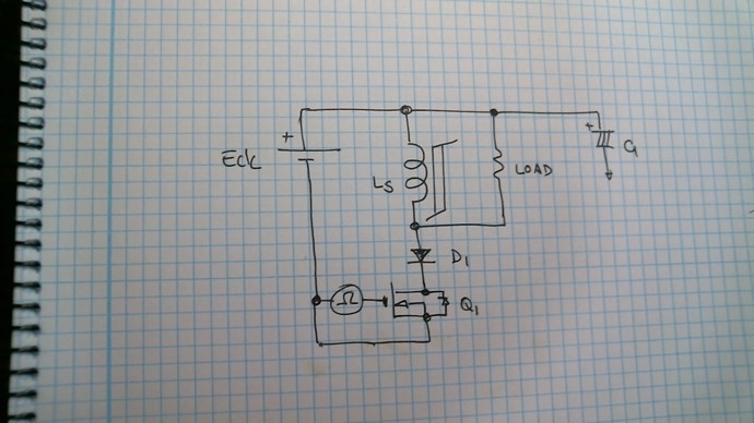
you solve it with a series diode directly in the drain of the mosfet, in this way
the parasitic diode inside it does not clamp during the Toff cycle.

Design a circuit to see what really happens, I publish it in your post
when it is finished and tested.

YoElMiCrO.

  • Liked by
  • Inception
Fighter posted this 23 June 2019

@YoElMiCrO:

You seem to have an very advanced background in mathematics and physics so of course your insights are very helpful, thanks.

I did read the document about Ferro-Kessor, first of all I wasn't aware of that by magnetizing a core its temperature drops.

I have few questions about your post:

  1. In your opinion are here the characteristics of an over-unity device ? Especially seeing the oscilloscope readings, did you saw something similar in other devices ? I'm asking this because for now even if i see the two 12V/25W halogen lights' luminosity I'm still struggling to figure out a way to get precise reading of the output; also even if I used DC source's readings and also an DC wattmeter reading there could be like 1% possibility to have inaccurate  readings on input too;
  2. Considering the very high frequency how is possible to have the core temperature dropping and then receiving temperature from environment in just a single cycle ? Does the core have enough time to do this in just miliseconds ?
  3. Do you think that in order to scale up ZPM using a bigger core is the only way ? I was thinking scaling up the coils could be a valid way too, eventually changing their turns ratio could be another possible way (right now it's approx. 1/2 - 150/300 turns;
  4. What are μ(max) and μ(inc)], I understand they are specific to the core ?

Thanks for the answers.

"If you want to find the secrets of the universe, think in terms of energy, frequency and vibration."
Nikola Tesla
  • Liked by
  • Inception
Fighter posted this 23 June 2019

@ Fighter.
Thanks for sharing your experiments.
What is happening to you may be buspumping, if that is
you solve it with a series diode directly in the drain of the mosfet, in this way
the parasitic diode inside it does not clamp during the Toff cycle.

YoElMiCrO.

You're welcome šŸ™‚

Is it possible to have impact on the DC source's readings and also in the same time on the DC wattmeter I used to verify the DC source's readings ? Could both be affected by something in the same time and show very wrong readings like miliampers instead of hundreds of milliamperes ?

"If you want to find the secrets of the universe, think in terms of energy, frequency and vibration."
Nikola Tesla
  • Liked by
  • Inception
YoElMiCrO posted this 23 June 2019

@ Fighter.

The reality is that it is always difficult to confirm the UA, but not impossible.
I'll analyze the waveforms to see what happens.
If I have seen anomalous behavior in some circuits.
The action by which the core auto-magnetizes is an intrinsic parameter of the core and
can go from the nano seconds to hours, you have to keep in mind that B should
remain constant and at a value where the permeability of the core is maximum.
That's why you need some way to control Ton.
Each core according to its mass will obtain a determined energy of the medium, but
Of course, increasing the number of turns also increases the inductance and
you must lower iL so that B is the one that maintains the maximum permeability.
μ(inc) is the permeability of the core just where the hysteresis curve becomes
linear and μ (max) is the maximum permeability achieved by said core for a value
of given magnetic field.
Today I will do tests to try to replicate the phenomenon and understand it, because I never tried
with bucking coils.

  • Liked by
  • Inception
Close