As I said here and in other threads showing successful experiments...
I'm making a copy here on our server of your ZPM replication video as a backup.
We know YouTube is unreliable and it can make any video disappear if it's showing something "inconvenient" 😉
It's too valuable to risk losing it.
They don't like when you have materials on your YouTube channel about zero-point energy or show experiments with "incovenient" results, about supressed technologies and inventions, about reverse-engineered technologies, black projects and ARVs (Alien Reproduction Vehicles)...
They don't specify the exact reasons ("We noticed some of your recent activity might not follow our rules.") but I know very well what they don't like. Also they're asking for video or ID identification in order to have the restrictions removed ! 😉
But it's okay, I have backups of the videos from my channel just in case they decide to shut it down.
That's why is always a good idea to have backups of your YouTube videos and having copies of the videos uploaded here on our site can also be considered an alternate backup to ensure the videos don't disappear forever (if they're only on YouTube).
For now the biggest issue is that I will not be able to add in the videos descriptions (for example videos with experiments) links to the threads here on our site containing details and data about these experiments:
Regards,
Fighter
"If you want to find the secrets of the universe, think in terms of
energy, frequency and
vibration."
Atti
posted this
20 June 2023
- Last Edited 20 June 2023
Hello everyone.
The reality is that your ZPM creates a virtual cloud [E] around him.
Also the fact that ZPM is sending energy back to the DC source should be taken into consideration, it will do the same with the batteries. Probably ZPM will try to "recharge" them, process which could damage them.
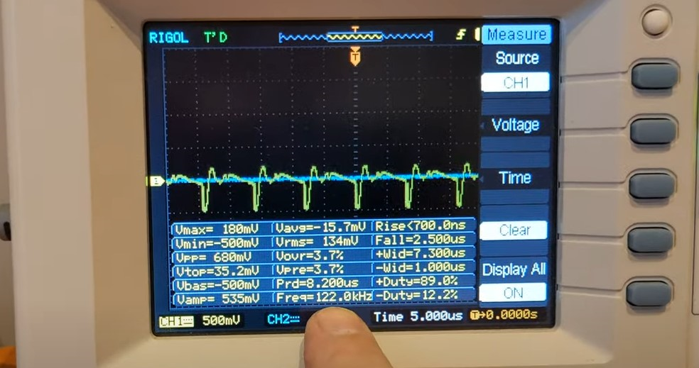
I fully agree. In the Cap5.akku video at 2:0.8 you can see the Deprez meter in the left corner showing the change when it is grounded or when it is not connected to ground. The path of the stray capacitance closure can fall into the path of the instrument (but then you have to be careful because all the components are under high voltage) At 3:20 you can see the voltage on the battery with the LED indicator. According to the excitation directions. Current and voltage values can be seen on an oscilloscope in the Cap4 utolsó felvétel video at 1:10. In my opinion it is an alternating voltage and is coming from the transformer. I am not sure if it is fully recharging the battery. This would need to be tested with a charge discharge diagram (postponed for the winter days due to lack of material and time)
The AC power meter should be inserted before the power supply. I agree with Yoel's suggestion. So the power coming from the power grid should be measured. But even so, you might still get a surprise because of the grounding (I referred to this under the Michro Generator question)
If this wiring diagram is indeed valid for Fighter's power supply then it may explain the modelling of stray capacitances ( I have already tried it partially)
I would ask Foghter to check to be sure that the power supply is indeed as shown in the schematic. So only the power supply cover should be removed. Of course only if you want to and if you have time!
Also. Don't forget. what I used is a completely different implementation. It is fitted with additional coils. But the gist is similar (the wiring diagram is everywhere).
That experiment needs to be redone with these variations.
In any case, it is absolutely correct. I agree with him and will continue on this path.
Even if the import of this thread is not complete I will continue the import as I'll find time.
For now I want to post some updates.
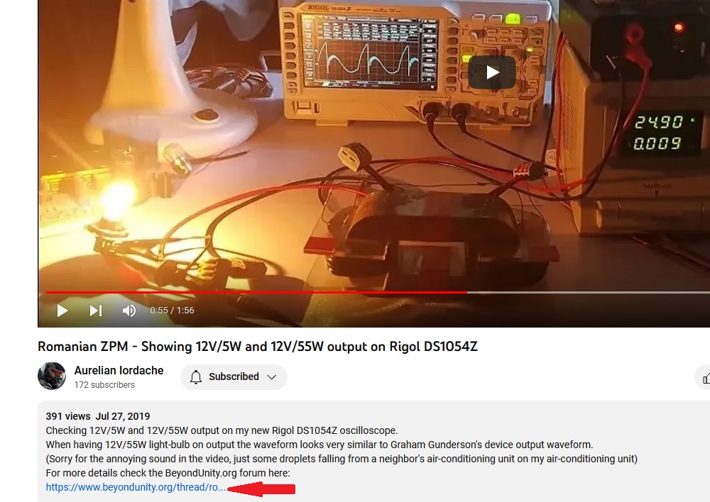
This weekend I took out from the boxes all the wires and my second ZPM and I put everything back on my experiments table but I didn't have time to organize for publishing the videos I recorded so I did it in this night.
First I just wanted to make sure everything still works:
Everything seems to be okay.
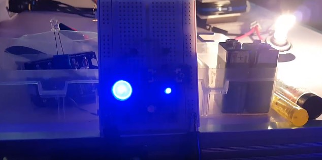
Then I checked something I wanted to check some time ago: I used the the tool I've built for my Aharonov-Bohm experiment to check the fields around ZPM but especially to confirm the presence of the standing waves on ZPM's output:
During the tests I found something very interesting about my replication of Jagau's Micro-Generator, while ZPM was running the Micro-Generator went crazy 😄
As a note: when I turn on the oscilloscope it seems to interfere with the Micro-Generator's functionality, it stops working. The cause is unknown for now.
It's true I saw it before blinking faster during rains or thunderstorms but I never saw it like this before:
We can see where ZPM is taking his extra-energy from. I don't think we're talking about just simply radio spectrum here.
ZPM's asymmetric and opposing magnetic fields at high frequency are disturbing the zero-point field. By disturbing the zero-point field, more energy becomes available in the area. Energy which the Micro-Generator is taking advantage of and it's harvesting it in the same time with the ZPM.
It's nice to see two totally different devices working together and using the same energy source (the zero-point field). ☺️
I used these videos in a bigger video I've made and uploaded on my channel about what happened in the past, how we've built our new platform here and about the the research our team is continuing here:
The ZPM enhancements research is resumed now and I'll continue it as I'll find time in parallel with other of my experiments (like the Aharonov-Bohm effect research) and replications related to SEC technologies presented by Jagau in his experiments.
Regards,
Fighter
"If you want to find the secrets of the universe, think in terms of
energy, frequency and
vibration."
Jagau
posted this
25 May 2023
- Last Edited 25 May 2023
Hi Fighter,
Nice video demonstration, we can see that the ZPM gives off a lot of electromagnetic radiation. the LED is continuous at full glow.
When you think about it, this energy that is free can be harvested in different ways, as D.Smith said, the ZPM is the transmitter and the microgen is a receiver.The question is how many receiver can we put without affecting the source? As much as you want! with real test done.
Hey Friends, Recently I made some tests related to noise , and found that there is some kind of it which is virtually impossible to filter or screen out.
So filtering the noise sent back by ZPM is impossible...
Also it is possible that a lot of power is dissipated in the low frequency rectifier.
This seems to be the case, the bridge rectifier and/or the transfomer become hot in about 10 minutes so those extra ~30W consumption shown by energy meters most probably are dissipated in that heat.
Regarding the change of the wave form of the ZPM when using the simple transformer, could it be a voltage drop the cause? There might be a threshold voltage for the ZPM to perform properly.As the lab PS is voltage stabilized, it is supposed to maintain the selected voltage, no so a standard transformer, there can be major variation depending on the load conditions.
This could be the case of voltage drop. I could make a test with the usual DC source by setting the voltage much below 25V and check how the waveform looks like.
I agree that a battery would give valuable comparison.
I will try this way, I will look for some local supliers for rechargable battery/batteries.
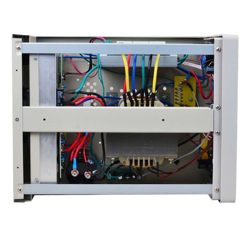
If it is actually some circuitry inside the PS that is interactive , it should be possible to find which components. Some time ago I had an issue with my PS , the current limiting was damaged, so I opened it to check, it is of the analogue type, a multi tapped steel core transformer, and linear voltage regulation, not switch mode type. I was a bit surprised about the few components on the output line, a single electrolytic capacitor , a precision current shunt, and a few more components. The only digital components are the voltage and current meters. I guess the Switch mode type PS has more filter components , to keep the switching noise low. But if Fighters PS is the analogue type, there are only a few possibilities of interacting components.
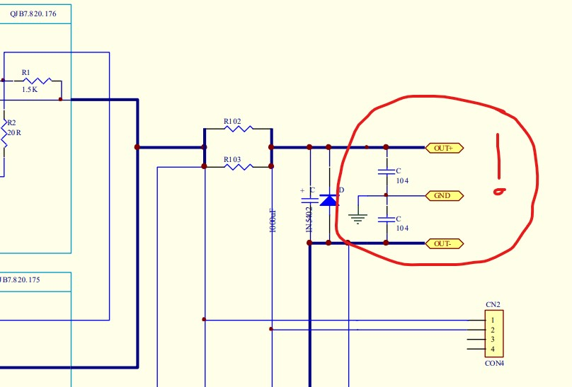
My DC source is switch-type, I remember I chosen it specifically to be this way, that's why is has about 16kg weight. The model is QJ6005E and the manufacturer's page is here:
Unfortunately there are no schematics anywhere on internet but I found a image from inside:
I see that big current-sensing shunt and also I see there are a lot of electronics, some of them could possibly actively working with ZPM but I have no idea which one.
On the manufacturer's site I see this option but it's for measurements when voltage drop occurs, I don't think it will help with high frequency noise:
By the way, I got a notice from costumes about a packet, this could be the metglass core, hopefully, now nearly four months ago was shipped from Europe. So maybe soon I can join the testing of the ZPM.
I would be glad if you could join the ZPM research, having another ZPM in experiments with different power source and measuring instruments will be very helpful in clarifying some aspects and ZPM's behavior !
@Atti
This is just an opinion, not to be accepted but to consider. In my opinion, the load on the transformer of a single DC source is probably too close to the maximum load. (36 VA) Therefore, the peak current draws too much down the buffer capacitor voltage. Whirring tension. Therefore, the input waveform on the secondary side of the individual transformer. If you could replace it with a larger transformer (maybe 200VA) waviness would decrease.
Another solution could be to use L-C filters before the ZPM input.
I agree, the voltage drop could be the reason for ZPM's behavior change, I'm taking this into consideration. I could try a test with the usual DC source but setting the voltage much lower than 25V and see how the waveform looks like. About filtering out the high-frequency noise sent back by ZPM, seems it's not a possible solution according to Vidura, seems this is a particular situation where filters don't work. I remember I tried with a choke coil on input and ZPM don't like that, I had extensive damage: DC source entered in auto-protection mode, the light bulbs on output burned and also the MOSFET was destroyed.
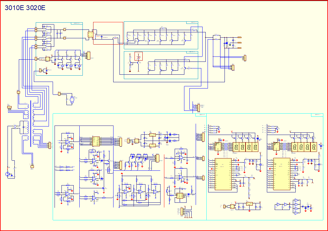
If you are using a factory lab power supply, then its wiring diagram would be good to know.
Unfortunately I could not find any schematics on internet for my DC source. You may find more details in my previous replies to Vidura.